Teaching experiment device making force method visualized
An experimental device and intuitive technology, applied in teaching models, educational appliances, instruments, etc., can solve problems such as insufficient understanding and doubts about related theories, and achieve the effect of small errors
- Summary
- Abstract
- Description
- Claims
- Application Information
AI Technical Summary
Problems solved by technology
Method used
Image
Examples
Embodiment 1
[0032] Example 1: A force method experiment based on an inverted "L"-shaped statically indeterminate rigid frame structure with one end fixed and the other free
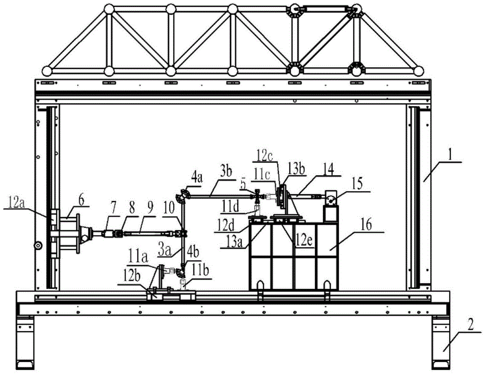
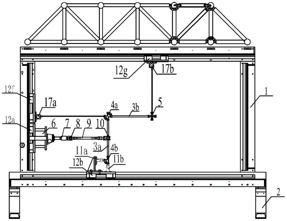
[0033] figure 2 It is the statically determinate basic structure diagram for the load of the force method teaching experimental device alone, figure 2 The structure is installed in the figure 1 the basis of the structure. One end of the horizontal stay wire displacement sensor 17a and the vertical stay wire displacement sensor 17b is fixed on the reaction force frame 1, and the other end is connected to the hinge point plate 5 by a stay wire. The worm gear loading device is connected to the vertical hollow square rod 3a to apply load, and at the same time, the corresponding displacement values are measured by the horizontal cable displacement sensor 17a and the vertical cable displacement sensor 17b.
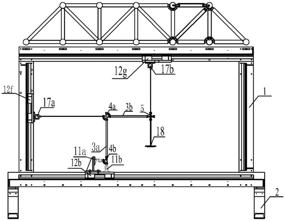
[0034] image 3 The basic structure diagram of the vertical reaction force acting alone on the static indete...
Embodiment 2
[0036] Example 2: Force method experiment with an inverted "L"-shaped primary statically indeterminate rigid frame structure with one end fixed and the other constrained vertical displacement as the basic structure
[0037] Figure 5 The load of the force method teaching experiment device acts on the primary statically indeterminate basic structure diagram alone. The rigid frame structure is formed by connecting two mutually perpendicular vertical hollow square rods 3a and transverse hollow square rods 3b through rigid joint plates 4a. One end of the vertical hollow square rod 3a is connected to the rigid joint plate 4a with a groove through a bolt; Connected; one end of the horizontal hollow square rod 3b is connected with the rigid joint plate 4a with a groove through a bolt; Connected hinges. The movable hinge support is installed on the box-shaped platform 16 and fixed on the lower beam of the reaction frame 1 . The horizontal stay wire displacement sensor 17a is fixed...
PUM
 Abstract
Description
Claims
Application Information
 - R&D
- Intellectual Property
- Life Sciences
- Materials
- Tech Scout
- Unparalleled Data Quality
- Higher Quality Content
- 60% Fewer Hallucinations
Browse by: Latest US Patents, China's latest patents, Technical Efficacy Thesaurus, Application Domain, Technology Topic, Popular Technical Reports.
© 2025 PatSnap. All rights reserved.Legal|Privacy policy|Modern Slavery Act Transparency Statement|Sitemap|About US| Contact US: help@patsnap.com


