Gas supply circuit used for controlling low-temperature gas-liquid connector

A connector and gas-liquid technology, applied in the direction of gas/liquid distribution and storage, pipeline systems, mechanical equipment, etc., can solve problems such as termination of the launch process, impact on the launch process, failure to achieve target requirements, etc., to improve reliability and improve The effect of job reliability

Active Publication Date: 2016-01-13
BEIJING INST OF SPACE LAUNCH TECH +1
View PDF5 Cites 0 Cited by
  • Summary
  • Abstract
  • Description
  • Claims
  • Application Information

AI Technical Summary

Problems solved by technology

[0002] At present, the solenoid valves used by cryogenic liquid rockets at home and abroad to provide control gas for cryogenic gas-liquid connectors are usually implemented with a single two-position five-way solenoid valve, which generally needs to continue to work until -2 minutes before launch, and is a single point without redundant design. In addition, once a failure occurs, it will directly affect the progress of the launch process, and even lead to the termination of the launch process, failing to achieve the goal of "zero window" launch in the mission.

Method used


Image

  • Gas supply circuit used for controlling low-temperature gas-liquid connector
  • Gas supply circuit used for controlling low-temperature gas-liquid connector
  • Gas supply circuit used for controlling low-temperature gas-liquid connector

Examples


Embodiment 1

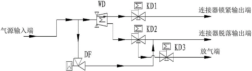
[0019] figure 1 It shows a schematic structural diagram of the gas supply circuit for the control of the low-temperature gas-liquid connector provided by Embodiment 1 of the present invention, see figure 1 , the gas supply circuit for the control of the low-temperature gas-liquid connector provided in Embodiment 1 of the present invention includes:

[0020] air source input;

[0021] Two-position five-way solenoid valve WD, the first end of the two-position five-way solenoid valve WD is connected to the air source input port;

[0022] The first normally open solenoid valve KD1, the first end of the first normally open solenoid valve KD1 is connected to the second end of the two-position five-way solenoid valve WD;

[0023] The second normally open solenoid valve KD2, the first end of the second normally open solenoid valve KD2 is connected to the third end of the two-position five-way solenoid valve WD;

[0024] The connector locking output end is connected to the second en...

Embodiment 2

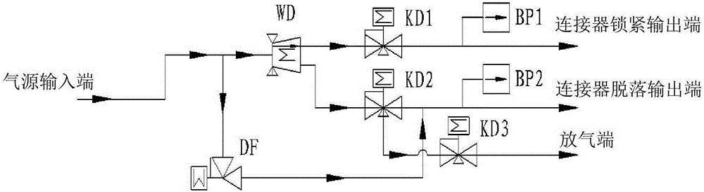
[0037] figure 2 It shows a schematic structural diagram of the gas supply circuit for the control of the low-temperature gas-liquid connector provided by Embodiment 2 of the present invention, see figure 2 In addition to all the components shown in Embodiment 1, the air supply circuit for the control of the low-temperature gas-liquid connector provided by Embodiment 2 of the present invention also includes: a first pressure sensor BP1 and / or a second pressure sensor BP2; in:

[0038] The first pressure sensor BP1 is arranged between the connector locking output end and the second end of the first normally open solenoid valve KD1;

[0039] The second pressure sensor BP2 is arranged between the output end of the connector disconnection and the second end of the second normally open solenoid valve KD2.

[0040] Wherein, the first pressure sensor BP1 and / or the second pressure sensor BP2 can monitor the working conditions of the gas supply circuit, that is, the first pressure ...

Embodiment 3

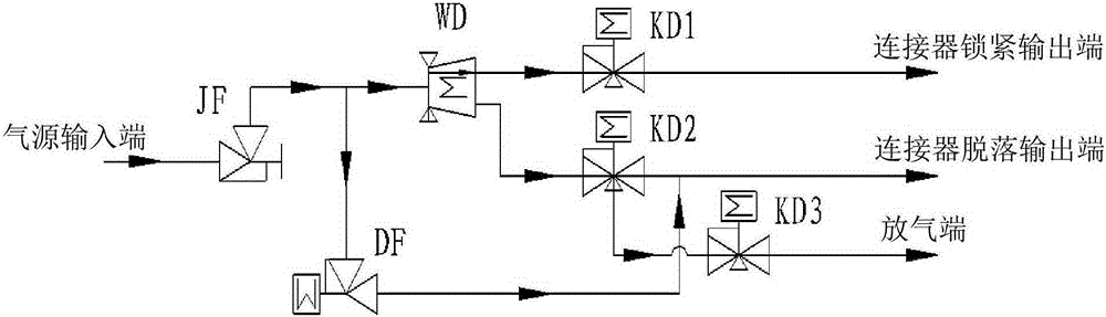
[0044] image 3 It shows a schematic structural diagram of the gas supply circuit for the control of the low-temperature gas-liquid connector provided by Embodiment 3 of the present invention, see image 3 In addition to all the components shown in Embodiment 1, the air supply circuit for the control of the low-temperature gas-liquid connector provided by Embodiment 3 of the present invention also includes: a manual shut-off valve JF;

[0045] The manual cut-off valve JF is arranged between the air source input end and the connection point between the first end of the two-position five-way solenoid valve WD and the first end of the two-position two-way solenoid valve DF.

[0046] Wherein, the manual shut-off valve JF can be an unloading manual shut-off valve, which can be used as an air source on-off valve for controlling the entire air supply circuit; the embodiment of the present invention sets the manual shut-off valve JF at the front end of the air supply circuit, In addi...


PUM


Abstract

The invention provides a gas supply circuit used for controlling a low-temperature gas-liquid connector. The gas supply circuit comprises a gas source input end, a two-position five-way electromagnetic valve, a first normally-open electromagnetic valve, a second normally-open electromagnetic valve, a connector locking output end, a connector disengagement output end, a third normally-open electromagnetic valve, a two-position two-way electromagnetic valve, and a gas exhaust end. The first end of the two-position five-way electromagnetic valve is connected with the gas source input end. The first end of the first normally-open electromagnetic valve is connected with the second end of the two-position five-way electromagnetic valve. The first end of the second normally-open electromagnetic valve is connected with the third end of the two-position five-way electromagnetic valve. The connector locking output end is connected with the second end of the first normally-open electromagnetic valve. The connector disengagement output end is connected with the second end of the second normally-open electromagnetic valve. The first end of the third normally-open electromagnetic valve is connected with the third end of the second normally-open electromagnetic valve. The first end of the two-position two-way electromagnetic valve is connected with the gas source input end. The second end of the two-position two-way electromagnetic valve is connected with the second end of the second normally-open electromagnetic valve. The gas exhaust end is connected with the second end of the third normally-open electromagnetic valve. According to the gas supply circuit, the design of redundant backup of the two-position five-way electromagnetic valve is provided for coping with possible failures, and the reliability of the gas supply circuit is improved.

Description

technical field [0001] The invention relates to the field of gas supply, in particular to a gas supply circuit for controlling a low-temperature gas-liquid connector. Background technique [0002] At present, the solenoid valves used by cryogenic liquid rockets at home and abroad to provide control gas for cryogenic gas-liquid connectors are usually implemented with a single two-position five-way solenoid valve, which generally needs to continue to work until -2 minutes before launch, and is a single point without redundant design. In addition, once a failure occurs, it will directly affect the progress of the launch process, and even lead to the termination of the launch process, failing to achieve the goal of "zero window" launch in the mission. Contents of the invention [0003] The present invention aims to overcome at least one of the above-mentioned defects and provide a gas supply circuit for the control of low-temperature gas-liquid connectors, which can be electri...

Claims


Application Information

Patent Timeline
IPC IPC(8): F17D1/04
Inventor 刘茜谢建明张韧刚张亚民代春涛王立何燚赵立乔贺建华
Owner BEIJING INST OF SPACE LAUNCH TECH
Why Eureka
Try Eureka