Multi-stage retractile pneumatic hydraulic ejection device

An ejection device, pneumatic-hydraulic technology, applied in the direction of fluid pressure actuation device, launching/dragging transmission device, servo motor, etc., can solve the problems of unguaranteed ejection speed, small ejection stroke, low ejection efficiency, etc., and achieve higher ejection speed And ejection efficiency, the effect of improving ejection speed

Active Publication Date: 2016-01-13
NANJING UNIV OF SCI & TECH
View PDF7 Cites 2 Cited by
  • Summary
  • Abstract
  • Description
  • Claims
  • Application Information

AI Technical Summary

Problems solved by technology

[0003] For example, the patent CN201010524849 proposes a single-stage gas-liquid mixed ejection method. During rapid ejection, the single-stage gas-liquid mixing cylinder is filled with a large flow of oil through the air bag accumulator, and the first-stage ejection extension end is mainly affected by the oil thrust and Negligible air resistance, so as to achieve high-speed ejection; at the same time, the device can realize the automatic retraction of the ejection piston rod under valve control; however, it is limited by the single-stage cylinder with a small effective ejection stroke and ultra-high-speed ejection (≥15m / s) Sealing cannot be guaranteed, preventing this ejection device from ejecting loads at ultra-high speeds
[0004] The patent CN200910166299 proposes an ejection device for a multi-stage gas-liquid mixing cylinder driven by high-pressure gas, which increases the effective ejection stroke in the form of a multi-stage cylinder, reduces the movement speed of adjacent two-stage cylinders, and avoids ultra-high-speed sealing However, this type of ejection device needs to use auxiliary equipment to realize the automatic retraction of the ejection mechanism after ejection, and because the initial ejection does not apply a preload force to the load and directly pushes the load to move laterally, the oil pressure cannot be quickly raised to the maximum Therefore, the power of the ejection extension rod is insufficient, the ejection speed cannot be guaranteed to reach a high level, and the ejection efficiency is low; in addition, since the ejection device uses oil with a closed oil chamber as the transmission medium, it can be ejected at high speed several times. After that, the internal oil will deteriorate and fail, and the ejection device does not provide an oil port for changing the oil

Method used


Image

  • Multi-stage retractile pneumatic hydraulic ejection device

Examples


Embodiment

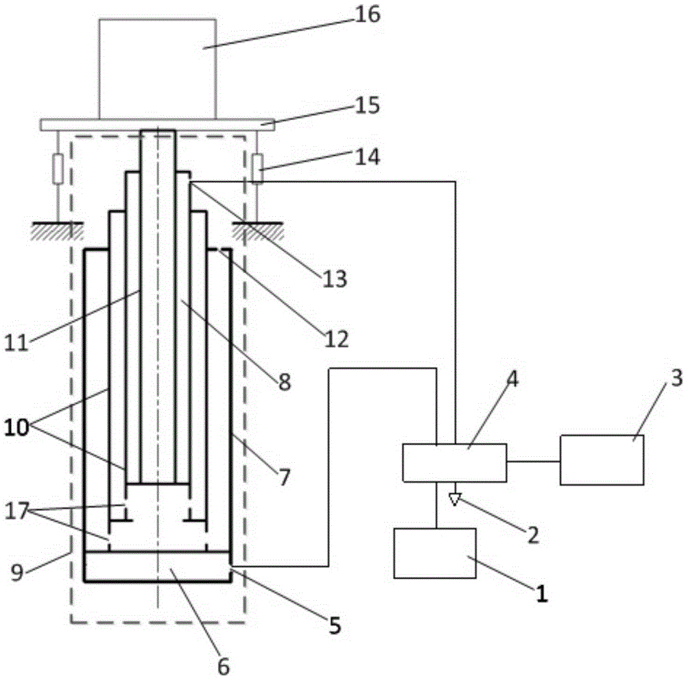
[0018] combine figure 1 :

[0019] A multi-stage retractable pneumatic-hydraulic ejection device, including a high-pressure air source 1, a controller 3, a pneumatic valve 4, a two-way gas-liquid mixing multi-stage cylinder 9, a pretensioning device 14, a bracket 15 and a load 16; wherein, The main cylinder body 7 of the two-way gas-liquid mixing multistage cylinder 9 is provided with a multistage sleeve type piston cylinder 10, and there is a cavity between the outer sleeve of the multistage sleeve type piston cylinder 10 and the inner wall of the main cylinder body 7. Filled with oil, the bottom of the multi-stage sleeve piston cylinder 10 is in sliding and sealing fit with the main cylinder body 7, and the open end of the main cylinder body 7 is in sliding and sealing fit with the multi-stage sleeve type piston cylinder 10, the multi-stage sleeve type The main gas chamber 6 is between the bottom of the piston cylinder 10 and the bottom of the main cylinder body 7. The mult...


PUM


Abstract

The invention discloses a multi-stage retractile pneumatic hydraulic ejection device. The output end of a high-pressure air source is connected with an air source input end of a pneumatic valve; a control signal output end of a control is connected with an electric input end of the pneumatic valve; two gas output ports of the pneumatic valve are separately connected with an air inlet of a bidirectional gas-liquid mixing multi-stage cylinder and an air port of the bidirectional gas-liquid mixing multi-stage cylinder; a load is arranged on a bracket; the bracket is fixedly connected with the end surface of an ejection extending rod of the bidirectional gas-liquid mixing multi-stage cylinder; and one end of a pre-tightening device is fixed, and the other end is connected with the bracket, so that a pre-tightening force in the direction opposite to the extending direction of the ejection extending rod is provided. According to the multi-stage retractile pneumatic hydraulic ejection device, the ejection efficiency is high; an ejection mechanism can be retracted automatically after ejection; and meanwhile, superspeed ejection can be realized by utilizing the multi-stage cylinder and the pre-tightening device.

Description

technical field [0001] The invention belongs to the field of pneumatic-hydraulic ejection devices, in particular to a multi-stage retractable pneumatic-hydraulic ejection device. Background technique [0002] Pneumatic-hydraulic ejection devices are widely used in military and civilian fields, such as the ejection of drones and missiles. [0003] For example, the patent CN201010524849 proposes a single-stage gas-liquid mixed ejection method. During rapid ejection, the single-stage gas-liquid mixing cylinder is filled with a large flow of oil through the air bag accumulator, and the first-stage ejection extension end is mainly affected by the oil thrust and Negligible air resistance, so as to achieve high-speed ejection; at the same time, the device can realize the automatic retraction of the ejection piston rod under valve control; however, it is limited by the single-stage cylinder with a small effective ejection stroke and ultra-high-speed ejection (≥15m / s) Sealing cannot...

Claims


Application Information

Patent Timeline
Patent Type & Authority Applications(China)
IPC IPC(8): F15B11/072B64F1/06
Inventor 任锐马大为刘铮
Owner NANJING UNIV OF SCI & TECH
Why Eureka
Try Eureka