Raft wave energy generating set with flexible structure

A technology of power generation device and structural wave, which is applied in the directions of ocean energy power generation, hydroelectric power generation, reaction engine, etc., can solve the problems of low energy absorption efficiency, few capacity conversion stages, low water level amplitude, etc., and achieves simple structure and long-term The effect of reliable operation, low manufacturing and maintenance costs

Inactive Publication Date: 2016-01-13
TIANJIN UNIV
View PDF4 Cites 7 Cited by
  • Summary
  • Abstract
  • Description
  • Claims
  • Application Information

AI Technical Summary

Problems solved by technology

In theory, this method has fewer stages of capacity conversion, which avoids energy loss in the process of multi-stage conversion, but its reliability in dealing with extreme weather conditions is poor.
3. To convert wave energy into flowing compressed air, and then generate electricity, the main method is to add a space structure connected to seawater in the breakwater. With the surge of waves, the water level rises and falls, and then drives the generator impeller to rotate, and finally drives The generator generates electricity. During use, the water level amplitude is low, and its energy absorption efficiency is relatively low.
The above-mentioned wave energy generation devices have their own advantages and disadvantages, and there is a need to improve the generation device and increase the power generation efficiency

Method used


Image

  • Raft wave energy generating set with flexible structure

Examples


Embodiment

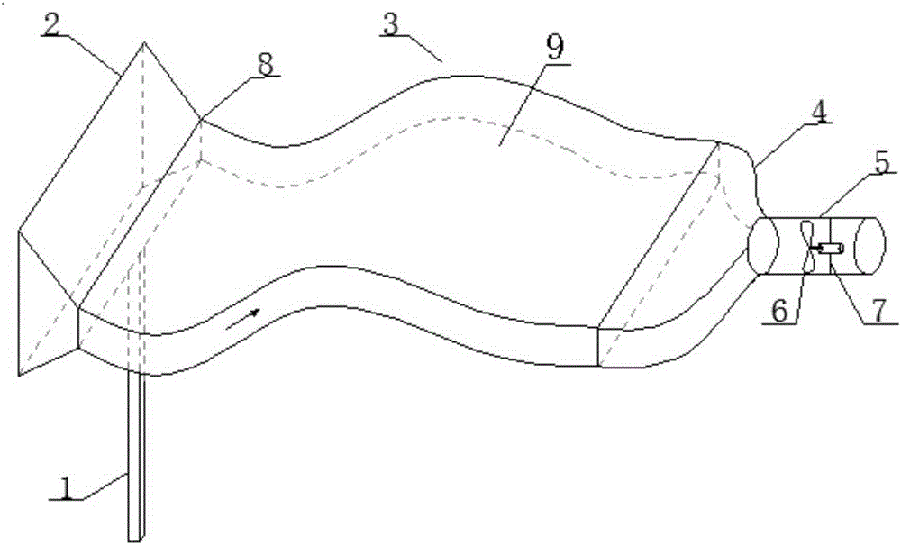
[0020] It mainly includes a fixed anchor rod 1, one or several rows of extremely elastic silicone tubes arranged side by side and a turbine generator 6 at its tail. Both ends of the silicone tube are open, and one end of the silicone tube is used for seawater to enter. Anchor rod 1 adopts a steel column. The height of the steel column should ensure that the entire raft-type flexible structure wave energy generating device can be immersed in water no matter whether it is high water level or low water level. The water inlet section 2 is mainly used to ensure that the mouth of the raft-type pulsation forming area 9 composed of a plurality of open cylindrical silicone tubes arranged side by side can enter water normally. There is a check valve 8 between them to ensure that the water flow can only enter and exit at this end; the other end of the silicone tube is arranged with a turbine generator 6, which is arranged inside the breakwater, on the one hand to collect the expansion wav...


PUM


Abstract

The invention discloses a raft wave energy generating set with a flexible structure. The raft wave energy generating set with the flexible structure comprises a turbine generator, an anchor rod, and an open type cavity made of a flexible material, wherein a bellmouth-shaped water inlet section is arranged at one end of the open type cavity, the turbine generator is arranged at the other end of the open type cavity, and the open type cavity is composed of a raft impulse forming region, an expansion wave energy collecting region and a wave energy converting region which are in sequential through connection from the water inlet section to a motor mounting region; the cross section of the expansion wave energy collecting region transits from large to small to the wave energy converting region from the raft impulse forming region; the motor mounting region is positioned at the tail end of the wave energy converting region; and the flowing of flow water drives the blades of the turbine generator to rotate, and further is converted into electric energy. The raft wave energy generating set provided by the invention has a simple structure, energy converting links are less, wave energy use ratio is improved greatly, the raft wave energy generating set also can be arranged in the front of a mole, so as to generate power on one aspect, and play a wave eliminating effect on the other aspect, and the wave-block pressure of the mole is alleviated greatly.

Description

technical field [0001] The invention relates to a wave power generating device, in particular to a wave energy generating device. Background technique [0002] As land-based resources are difficult to meet the needs of the development of human society, countries all over the world regard marine renewable energy as a strategic resource to solve energy shortages and address climate change. Especially in the 21st century, facing the increasing scarcity of fossil energy such as coal and oil and the enormous pressure of reducing environmental pollution and coping with climate change, the international community has reached a consensus on the strategic position of marine renewable energy in the future energy field. Development and utilization has become one of the important contents of global high-tech in the 21st century. [0003] As a clean and renewable energy source, wave energy has been studied by humans as early as a century ago, but the wave energy research at that time wa...

Claims


Application Information

Patent Timeline
IPC IPC(8): F03B13/22F03B3/18
CPCY02E10/20Y02E10/30
Inventor 余海涛白志刚杨武戴磊
Owner TIANJIN UNIV
Why Eureka
Try Eureka