
Sewage treatment integrated device enabling gravitational self-refluxing of activated sludge

A technology for sewage treatment and activated sludge, which is used in water/sludge/sewage treatment, biological water/sewage treatment, sustainable biological treatment, etc. Unable to set the adjustment pool and other problems

Active Publication Date: 2016-01-13
THUNIP CORP LTD +1
View PDF6 Cites 2 Cited by
  • Summary
  • Abstract
  • Description
  • Claims
  • Application Information

AI Technical Summary

Problems solved by technology

[0002] There are many types of integrated sewage biochemical treatment devices at present, but most of them still use the layout of traditional technology. Some functions are insufficient. For example, the sedimentation tank is generally a separate grid, and the length of the inlet and outlet weirs is limited and short, resulting in a large amount of water per unit weir width, which affects the water outlet effect.
In addition, the general integrated treatment device is limited by volume, and it is impossible to install a regulating tank inside the device itself, so that the device does not have the function of flow regulation, so generally this kind of device excludes the pretreatment and water volume regulation functions from the integrated device. On-site additional construction, resulting in increased investment and land occupation, and inconvenient management and application

Method used


Image

  • Sewage treatment integrated device enabling gravitational self-refluxing of activated sludge
  • Sewage treatment integrated device enabling gravitational self-refluxing of activated sludge
  • Sewage treatment integrated device enabling gravitational self-refluxing of activated sludge

Examples


Embodiment Construction

[0023] The specific implementation manners of the present invention will be further described in detail below in conjunction with the accompanying drawings and embodiments. The following examples are used to illustrate the present invention, but are not intended to limit the scope of the present invention.

[0024] In the description of the present invention, it should be noted that the terms "center", "longitudinal", "transverse", "upper", "lower", "front", "rear", "left", "right", " The orientations or positional relationships indicated by "vertical", "horizontal", "top", "bottom", "inner", "outer", etc. are based on the orientation or positional relationships shown in the drawings, and are only for the convenience of describing the present invention and simplifying Describes, but does not indicate or imply that the device or element referred to must have a specific orientation, be constructed in a specific orientation, and operate in a specific orientation, and therefore sh...


PUM


Abstract

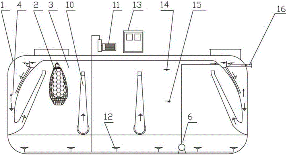
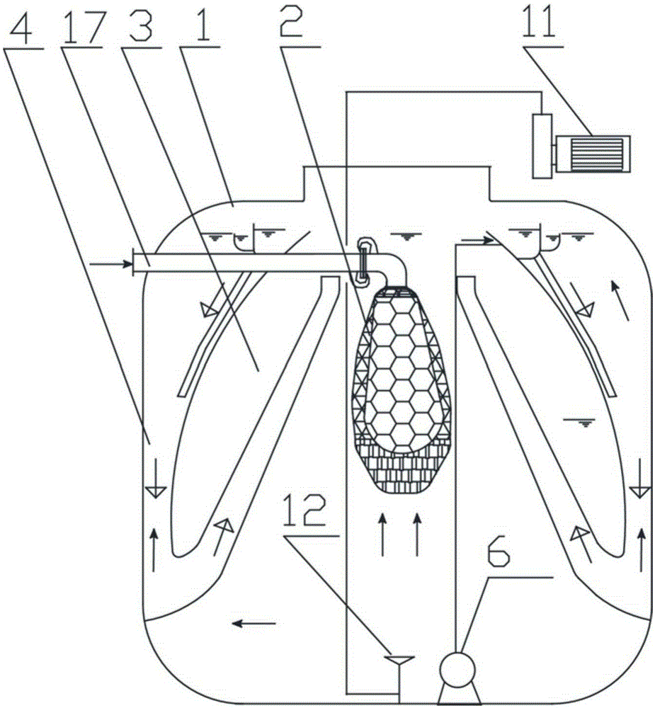
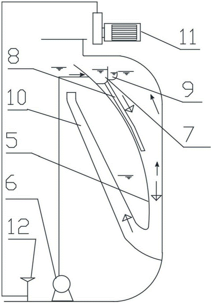
The invention relates to the field of sewage treatment, and discloses a sewage treatment integrated device enabling gravitational self-refluxing of activated sludge. The device comprises an integrated treatment tank which is internally provided with a circularly arranged partitioning guide plate and is divided into a biochemical region and a settling region; the biochemical region is positioned in a region surrounded by the partitioning guide plate, and the settling region is positioned in a region surrounded by the partitioning guide plate and the wall of the integrated treatment tank; the lower end of the partitioning guide plate inclines toward the wall of the integrated treatment tank and is connected with the wall; a plurality of sludge gravitational refluxing pipes communicating with the bottom of the settling region are arranged in the periphery of the partitioning guide plate; a water inlet chute which is peripherally arranged is formed in the upper part on the outside of the partitioning guide plate; an effluent weir slot which is lower than the opening of the water inlet chute is arranged at the periphery of the water inlet chute; a drain pump is arranged in the bottom of the biochemical region; the drain pump is connected to the water inlet chute through a pipeline. The device disclosed by the invention is convenient in structural configuration and operation management, so that the effluent effect is improved while the occupied area and the investment cost are reduced.

Description

technical field [0001] The invention relates to the technical field of sewage treatment, in particular to an activated sludge gravity self-reflux sewage treatment integrated device. Background technique [0002] There are many types of integrated sewage biochemical treatment devices at present, but most of them still use the layout of traditional technology. Some functions are not fully utilized. For example, the sedimentation tank is generally a separate grid, and the length of the inlet and outlet weir channels is limited and short, resulting in a large amount of water per unit weir width, which affects the water outlet effect. In addition, the general integrated treatment device is limited by volume, and it is impossible to install a regulating tank inside the device itself, so that the device does not have the function of flow regulation, so generally this kind of device excludes the pretreatment and water volume regulation functions from the integrated device. On-site ...

Claims


Application Information

Patent Timeline
Patent Type & Authority Applications(China)
IPC IPC(8): C02F3/00C02F3/12
CPCY02W10/10
Inventor 王旭李星文李京莲周丽颖袁琳
Owner THUNIP CORP LTD
Learn More