Hydraulic positioning clamping mechanism for shaft machining

A clamping mechanism and hydraulic positioning technology, which is applied to metal processing machinery parts, positioning devices, metal processing equipment, etc., can solve the problems of uneven technology, reliability, stability, and durability, lack of sensibility, rational understanding and deep Issues such as lack of in-depth research on basic knowledge and development direction

Inactive Publication Date: 2016-01-13
WUXI QINGYANG MACHINERY MFG
View PDF7 Cites 5 Cited by
  • Summary
  • Abstract
  • Description
  • Claims
  • Application Information

AI Technical Summary

Problems solved by technology

[0007] 2. In terms of basic skills, the familiarity with the user's production needs and the understanding of the user's product processing technology are poor
Lack of in-depth research on the future development direction; many key technologies of machine tools such as machinery, electricity, hydraulics, gas, light, components, functional components, NC systems, hardware, software, etc. have not been grasped, and they are not technically qualified; The fundamental points of the development of machine tool technology, such as: technology, precision, efficiency, automation, intelligence, environmental protection, and networking, lack key points for in-depth grasp and comprehensive penetration
[0008] 3. The design, manufacture, use, and innovation capabilities of China's mac

Method used


Image

  • Hydraulic positioning clamping mechanism for shaft machining

Examples


Embodiment 1

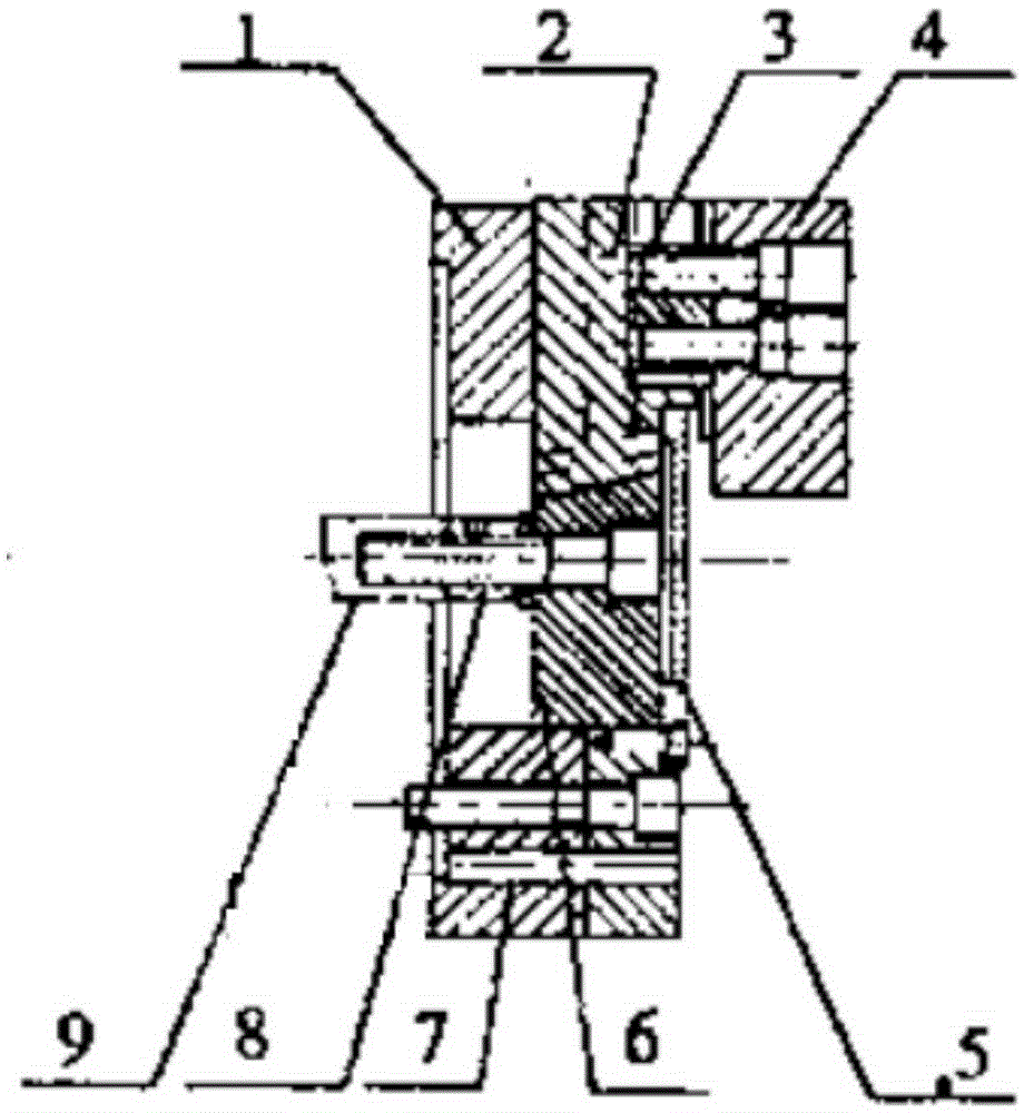
[0021] The clamping mechanism is composed of three clamping claws. The angle between two clamping claws is 120°. The joint shaft 6 is connected with the hydraulic piston rod 9 through bolts. The joint shaft 6 is designed to be clamped at 20° with the horizontal axis. Angular dovetail structure, and is connected with the translation base 2, the hydraulic piston rod 9 drives the joint shaft 6 to move left and right by moving left and right, and at the same time, the translation base 2 has an inclination angle with the contact surface of the joint shaft 6, so that the translation base The seat 2 moves centripetally or centrifugally along the radial direction. The baffle plate 5 is connected with the cylindrical disc 1 through bolts to prevent dust from falling into the joint shaft 6, and the hydraulic piston rod 9 has a sealing ring 8 to isolate the liquid medium in the hydraulic cylinder. The clamping jaw base 4 is connected with the translation base 2 through the bolt 3, so tha...


PUM


Abstract

The invention discloses a hydraulic positioning clamping mechanism for shaft machining. The clamping mechanism comprises three clamping claws; an included angle of 120 degrees is formed between every two adjacent clamping claws; a joint shaft 6 is connected with a hydraulic piston rod 9 through a bolt; a dovetail groove structure which forms a 20-degree included angle with the horizontal axis is designed on the joint shaft 6; the joint shaft 6 is in match connection with a translation base 2; the hydraulic piston rod 9 drives the joint shaft 6 to move left and right through left and right moving; and meanwhile, an inclined angle is formed between the contact surface of the translation base 2 and the joint shaft 6 and the horizontal plane, so that the translation base 2 does centred motion or centrifugal motion along the longitudinal direction. A baffle plate 5 is connected with a cylindrical disc 1 through bolts, so that dust is prevented from falling into the joint shaft 6; and the hydraulic piston rod 9 is provided with a sealing ring 8, so that a liquid medium in a hydraulic cylinder is isolated. A clamping claw base 4 is connected with the translation base 2 through bolts 3, so that the clamping claw 4 moves along with the movement of the translation base 2; and connection threaded holes are formed in the clamping claw base 4, so that different clamping claws can be changed according to different workpieces.

Description

technical field [0001] The invention relates to the field of machining design and manufacture of mechanical shafts, in particular to a hydraulic positioning and clamping mechanism for machining shafts. Background technique [0002] Machine tool is a modern complex production tool, and it is one of the most important elements among the three elements of human production and development (people, tools, resources). People create tools, rationally use resources, and the quality of people and the level of technology are the basis for social development. and fundamental motivation. The "advanced nature" of the tools created by people determines the production efficiency and labor productivity in the production of various industries in industry and agriculture. For example: the United States currently has the highest personnel quality and technological level in the world, about half of which are college graduates, and it recruits elite talents from all over the world. The product...

Claims


Application Information

Patent Timeline
IPC IPC(8): B23Q3/08B23Q11/00
CPCB23Q3/082B23Q11/00
Inventor 唐靖岚
Owner WUXI QINGYANG MACHINERY MFG
Why Eureka
Try Eureka