Energy guiding chain

A technology of energy guide chains and components, applied in the field of energy guide chains, which can solve problems such as insufficient realization and difficulty, and achieve the effect of easy insertion and replacement, and good sealing

Active Publication Date: 2016-01-06
IGUS
View PDF5 Cites 0 Cited by
  • Summary
  • Abstract
  • Description
  • Claims
  • Application Information

AI Technical Summary

Problems solved by technology

Sealing between the top and bottom walls of adjacent chain links can only be achieved with difficulty or insufficiently in the region of the stepped contact surfaces

Method used


Image

  • Energy guiding chain
  • Energy guiding chain
  • Energy guiding chain

Examples


Embodiment Construction

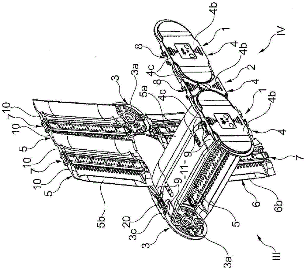
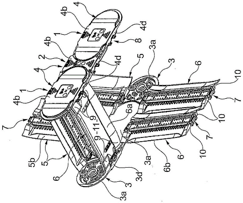
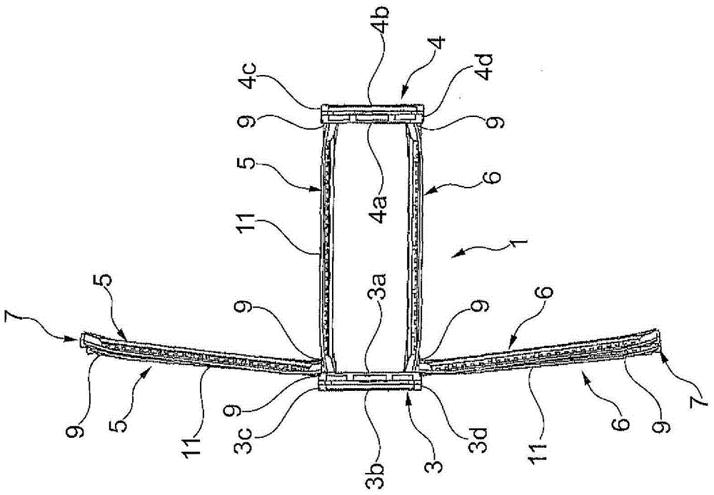
[0045] exist figure 1 The part of the energy guide chain / energy chain shown in is composed of three chain links, wherein the outer chain link 1 comprises opposite side straps 3 which overlap the side straps 4 of the inner chain link 2 on the outside. The side straps 3 and 4 form opposing strap bundles transversely to their longitudinal direction, which continue over the entire length of the energy conducting chain.

[0046] The energy guide chain / energy chain comprises a plurality of chain links 1, 2 which are pivotable relative to each other within a certain pivot angle and which extend from a first connection point (not shown in the figure) to A second connection point (not shown in the figure) movable relative to the first connection point.

[0047] as from figure 1 and 2 It can be seen that each side strap 3, 4 comprises an inner side 3a, 4a facing the inside of the chain, an outer side 3b, 4b facing outwards, and a side strap perpendicular to said inner side and said o...


PUM


Abstract

The invention relates to an energy guiding chain, the chain links thereof (1, 2) having two side plates (3, 4) each which are joined together by transverse rods (5, 6). Said transverse rods comprise on at least one of the ends thereof, a bearing area (7), and when seen in the longitudinal direction of the side plates (3, 4), has a contact area (9) which is outside of the bearing area. In order to prevent the accumulation of foreign bodies, the side (11) of the contact area of the transverse rods pointing from the inside of the chain to the outside is convexly curved inwards or is linearly inclined to the bearing surface (10) thereof and forms an angle, with the inner side (3a, 4a) of the respective side plate, which is less than 90 DEG C such that said bearing surface (10), when pivoting the traverse rod until a fully open position is reached, moves inwards along the inner side of the side plate to the inside of the chain.

Description

technical field [0001] The invention relates to an energy guide chain for guiding cables, hoses etc. from a first connection point to a second connection point moving relative to the first connection point, the energy guide chain comprising a plurality of pivoting plastic links each comprising two side straps comprising an inner side facing the inside of the chain, an outer side facing outward and perpendicular to the inner side and the outer side and A narrow face extending in the longitudinal direction of the side straps, wherein the side straps form opposing strap bundles transversely to their longitudinal direction, and at least some of the opposing side straps are connected to each other by transverse members of which At least some of their ends comprise a load-bearing area on at least one of their ends, which interacts in an articulated manner with a bearing seat on a side strap facing the aforementioned end of the traverse member, so that the traverse member is in the c...

Claims


Application Information

Patent Timeline
IPC IPC(8): F16G13/16H02G3/04H02G11/00
CPCF16G13/16H02G3/0475H02G11/006H02G3/04
Inventor A·赫尔迈T-A·耶克尔S·施特拉克
Owner IGUS
Why Eureka
Try Eureka