
Directional antenna

A directional antenna and straight line technology, applied to antennas, antenna unit combinations with different polarization directions, independent antenna unit combinations, etc., can solve the problems of antenna production and installation inconvenience, production and installation inconvenience, signal interference, etc., to reduce Effects of signal interference, improving user experience, and improving signal quality

Active Publication Date: 2019-10-25
KUANG CHI INST OF ADVANCED TECH
View PDF4 Cites 0 Cited by
  • Summary
  • Abstract
  • Description
  • Claims
  • Application Information

AI Technical Summary

Problems solved by technology

[0006] Aiming at the problems of signal interference signals and too many feeder interfaces in the existing WIFI directional ceiling antennas that cause inconvenience in production and installation, the present invention proposes a directional antenna that can avoid signal interference in different frequency bands and effectively improve signal quality. Improve user experience, and at the same time avoid too many feeder interfaces, which cause inconvenience in antenna production and installation

Method used


Image

  • Directional antenna
  • Directional antenna
  • Directional antenna

Examples


Embodiment Construction

[0030] The following will clearly and completely describe the technical solutions in the embodiments of the present invention with reference to the accompanying drawings in the embodiments of the present invention. Obviously, the described embodiments are only some, not all, embodiments of the present invention. All other embodiments obtained by persons of ordinary skill in the art based on the embodiments of the present invention belong to the protection scope of the present invention.

[0031] According to an embodiment of the present invention, a directional antenna is provided, and the antenna may be a WLAN antenna, or an antenna for transmitting and receiving signals through other methods or protocols.

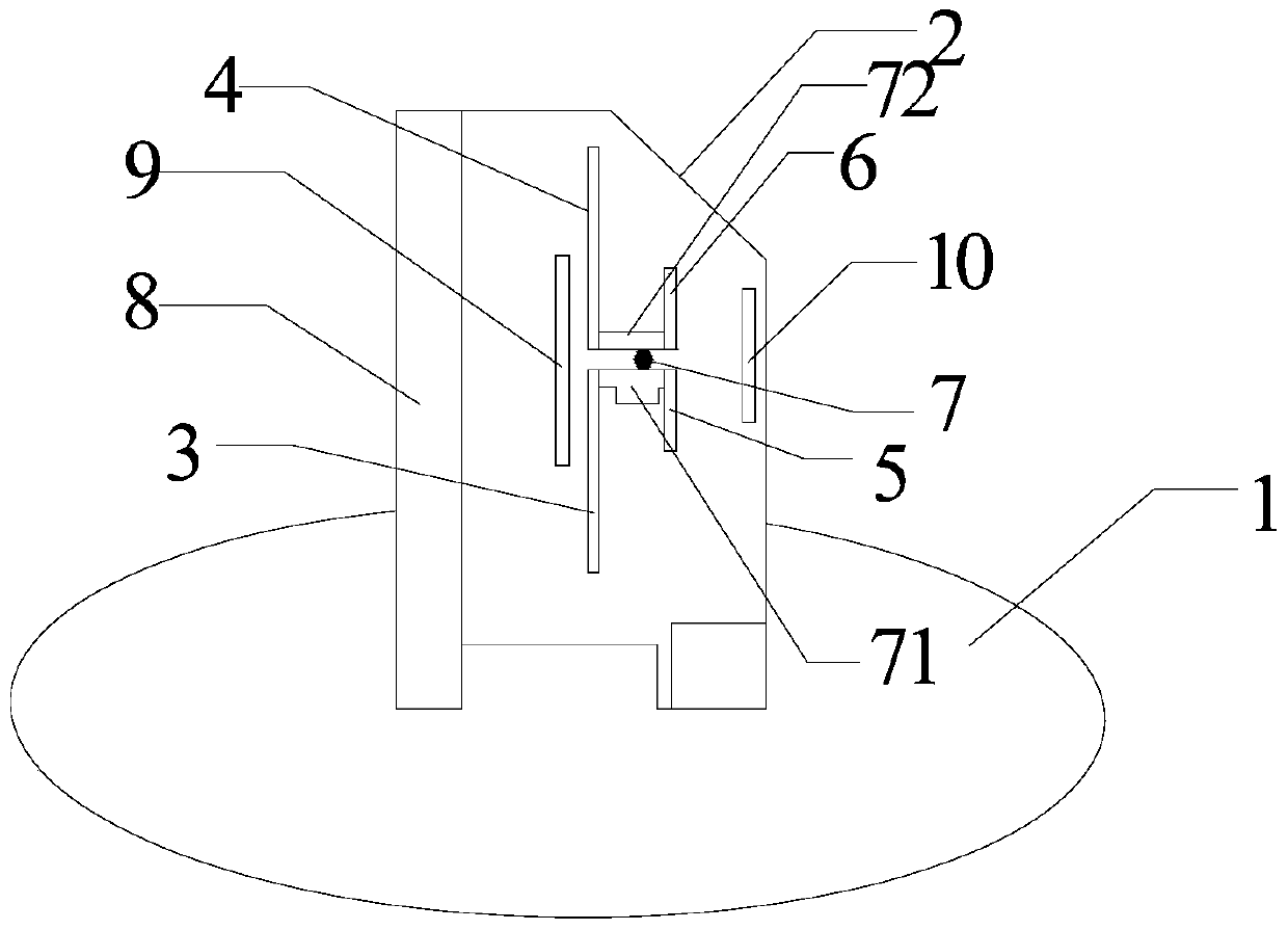
[0032] Such as figure 1 As shown, the directional antenna according to the embodiment of the present invention includes a base plate 1 and a dielectric plate 2, wherein the dielectric plate 2 stands on the base plate 1, and the dielectric plate 2 is provided with: a feed ...


PUM


Abstract

The invention discloses a directional antenna, which comprises a bottom plate and a dielectric plate. The dielectric plate is erected on the bottom plate. The dielectric plate is provided thereon with a feed balun, a first polaron, a second polaron, a third polaron, a fourth polaron, a first signal reflection mechanism, a second signal reflection mechanism and a signal direction guiding mechanism. The first polaron and the second polaron are configured to run within a first frequency band. The third polaron and the fourth polaron are configured to run within a second frequency band. The first signal reflection mechanism is positioned on one side of the first polaron and the second polaron. The second signal reflection mechanism is positioned on one side of the third polaron and the fourth polaron. The signal direction guiding mechanism is positioned on the other side of the third polaron and the fourth polaron. The first polaron, the second polaron, the third polaron and the fourth polaron are connected with the feed balun. According to the invention, different polarons arranged on the same dielectric plate share the single feed balun and are configured to run within different frequency bands. Meanwhile, signals of different frequency bands are reflected and guided in direction by two signal reflection mechanisms and one signal direction guiding mechanism. Therefore, a dual-band and single-feed directional ceiling-mounted antenna is realized.

Description

technical field [0001] The present invention relates to the field of antennas, and in particular, to a directional antenna. Background technique [0002] With the advancement of technology and the increasing popularity of smart phones, people's demand for wireless WIFI access is increasing. For example, WIFI coverage is required in homes, offices, exhibition halls, shopping malls, etc., which requires excellent signal coverage to provide users with Provide high-speed, high-quality Internet experience. In some special occasions, some places are narrow and long (for example, a subway aisle), therefore, it is necessary to use a directional antenna to ensure excellent signal coverage. [0003] However, the 2.4GHz / 5.8GHz dual-frequency dual-feeder structure is commonly used in the current WIFI directional ceiling antennas on the market. When this 2.4GHz / 5.8GHz dual-frequency dual-feeder structure is used, it passes the The corresponding independent feeder interface is used for ...

Claims


Application Information

Patent Timeline
Patent Type & Authority Patents(China)
IPC IPC(8): H01Q21/24H01Q21/30H01Q19/00H01Q19/185H01Q1/38H01Q1/50
Inventor 不公告发明人
Owner KUANG CHI INST OF ADVANCED TECH
Learn More