Overall battery formation technological process system
A technology for battery formation and process flow, applied in the field of the overall battery formation process system, can solve the problem of high labor intensity, reduce labor intensity, ensure physical health, and avoid difficulty in transportation of goods
- Summary
- Abstract
- Description
- Claims
- Application Information
AI Technical Summary
Problems solved by technology
Method used
Image

Examples
Embodiment 1
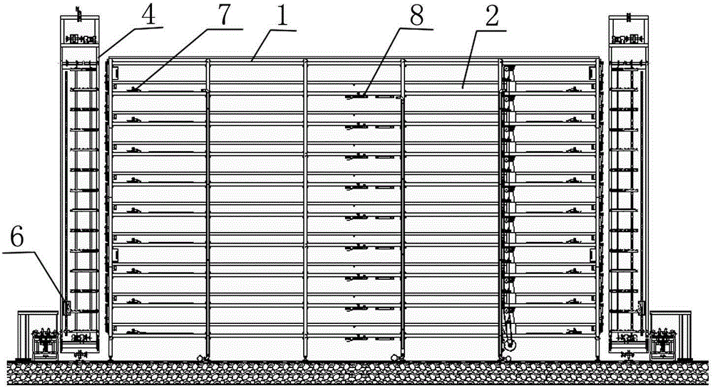
[0046] The overall battery formation process system, such as figure 1 and figure 2 As shown, it includes a formation rack 1, a formation tank 2 with gaps at both ends installed on the formation rack 1, a horizontal transport system 3 fixed on the formation rack 1 for horizontal transportation of batteries in the formation tank 2, and lifting the battery to the corresponding formation tank. The lifting mechanism 4 at the notches at both ends of the tank 2, the valve closing structure 5 at the notches at both ends of the forming tank 2, and the conveying mechanism 6 that enables the batteries on the lifting mechanism 4 to enter the forming tank 2 or move out of the forming tank 2.
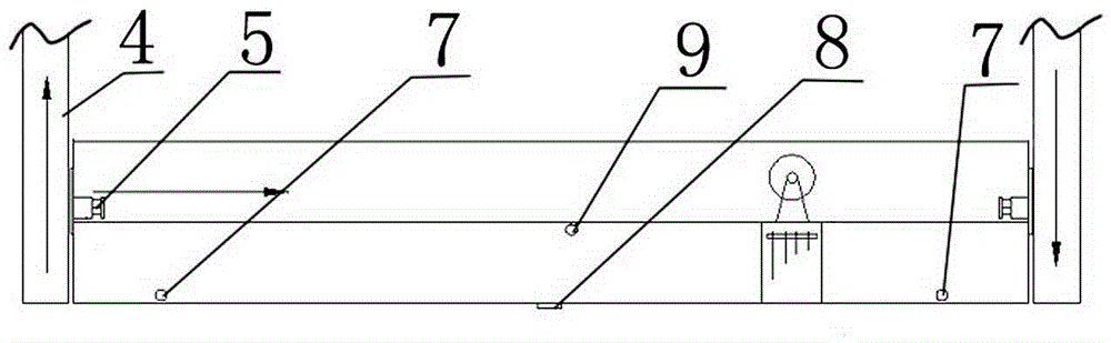
[0047] In the present invention, a water inlet 7 is provided at the bottom of the side wall of the chemical conversion tank 2 , a water outlet 8 is provided at the bottom of the chemical conversion tank 2 , and an overflow port 9 is provided at the top of the side wall of the chemical conversion tan...
Embodiment 2
[0070] The difference between this embodiment and Embodiment 1 is: in this embodiment, the specific setting method of the lifting mechanism 4 is optimized, such as Figure 5 and Figure 6 As shown, the specific settings are as follows:
[0071] There are two top sprockets 421, bottom sprockets 422 and lifting chains 423 in the lift chain group 42, the two top sprockets 421 are fixedly connected by concentric shafts, and the two bottom sprockets 422 are also fixed by concentric shafts. Connected, two lifting chains 423 are arranged in parallel between the top sprocket 421 and the bottom sprocket 422; the two ends of the lifting pallet 43 are respectively fixed on the two lifting chains 423.
[0072] Wherein, the lifting chain group 42 is also arranged in two, and is installed on the mounting bracket 41 in parallel and symmetrically in the vertical direction; the two lifting pallets 43 adjacent to each other between the two lifting chain groups 42 are located on the same horizo...
Embodiment 3
[0076] The difference between this embodiment and Embodiment 1 is that this embodiment provides another specific setting method of the transverse transmission device, and the specific setting method of the transverse transmission device in this embodiment is as follows:
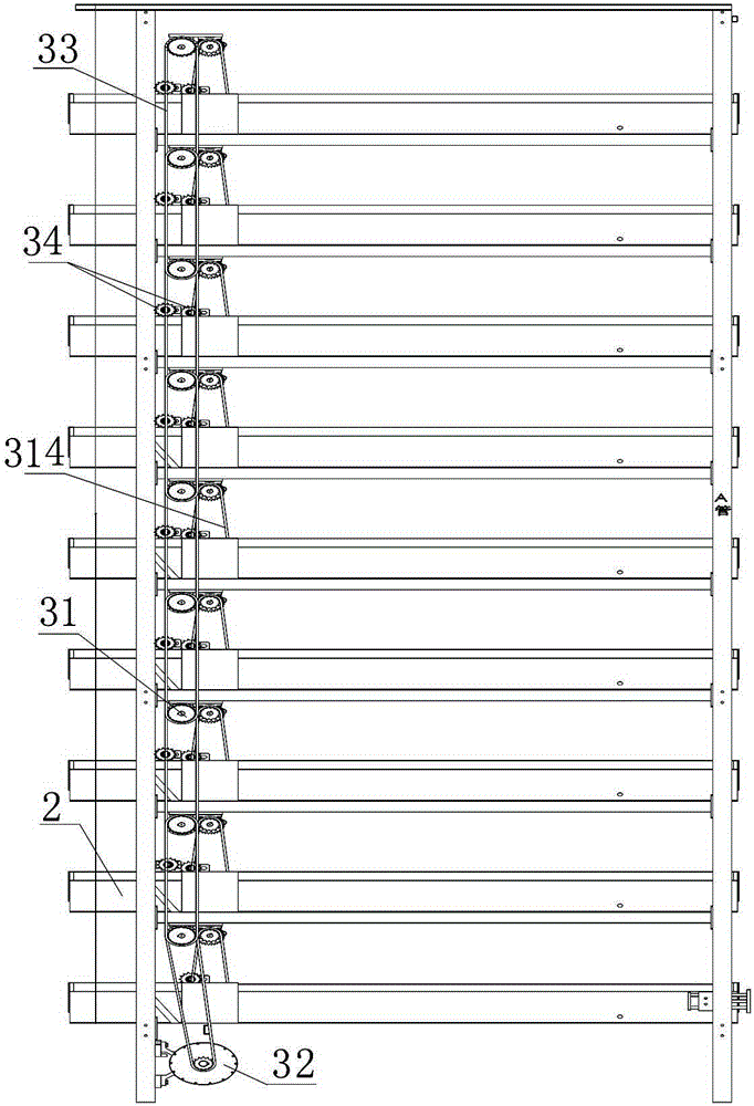
[0077]Wherein, the transverse transmission device includes a transmission sprocket connected to the transmission input wheel 313 in the groove by driving the chain 33, and a chain conveying mechanism fixed on the sprocket shaft of the transmission sprocket; The driving steering wheel group on the sprocket shaft, the driven steering wheel group that is arranged on the other end of the groove 2, the chain group that connects the driving steering wheel group and the driven steering wheel group, and the bearing platform fixed on the chain group.
[0078] That is, the active steering wheel set is composed of active steering wheels installed at both ends of the same rotating shaft, the structure of the driven steeri...
PUM
 Abstract
Description
Claims
Application Information
 - R&D
- Intellectual Property
- Life Sciences
- Materials
- Tech Scout
- Unparalleled Data Quality
- Higher Quality Content
- 60% Fewer Hallucinations
Browse by: Latest US Patents, China's latest patents, Technical Efficacy Thesaurus, Application Domain, Technology Topic, Popular Technical Reports.
© 2025 PatSnap. All rights reserved.Legal|Privacy policy|Modern Slavery Act Transparency Statement|Sitemap|About US| Contact US: help@patsnap.com