
Self-propelled hydraulic T-shaped beam prefabricating template device and demolding method thereof

A self-propelled, formwork technology, applied in the direction of unloading devices, molds, manufacturing tools, etc., to achieve the effect of reducing production costs, coordinated and consistent actions, and saving time and effort in automation

Active Publication Date: 2016-01-06
SHANDONG TIEYING CONSTR ENG
View PDF3 Cites 16 Cited by
  • Summary
  • Abstract
  • Description
  • Claims
  • Application Information

AI Technical Summary

Problems solved by technology

When the formwork has reached the design demolition strength, when this method is used to remove the side formwork, each half of the side formwork is pulled synchronously by manpower using four ratchet wheels and the side formwork is tilted and separated from the concrete surface. This process requires The action of the ratchet wheels is coordinated. If the adjustment of each ratchet wheel is inconsistent or out of sync, it will increase the demoulding resistance and increase the deformation of the template, reducing the service life of the template
The separation process of the side formwork and the T-beam requires manual and synchronous adjustment of the ratchet wheel, and requires the ratchet wheel to move in unison, so the process of removing the formwork is time-consuming and laborious and has a low degree of automation; at the same time, when moving longitudinally, an external winch is used for traction. The overall integration of the device is low

Method used


Image

  • Self-propelled hydraulic T-shaped beam prefabricating template device and demolding method thereof
  • Self-propelled hydraulic T-shaped beam prefabricating template device and demolding method thereof
  • Self-propelled hydraulic T-shaped beam prefabricating template device and demolding method thereof

Examples


Embodiment Construction

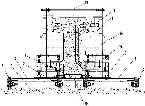
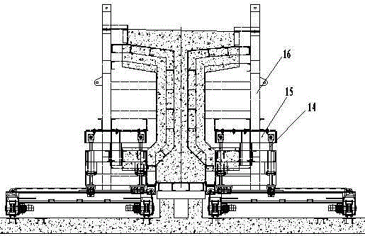
[0021] Figure 1-6 As an embodiment of the present invention, this embodiment is specifically described in conjunction with the accompanying drawings, including a formwork device composed of a side form device 1, an end form device 2 and a bottom form device 3, on the concrete foundation surfaces on both sides of the side form device 1 Guide rails 5 are set, frame-type longitudinally moving car bodies 8 are installed on the guide rails 5 on both sides of the frame-type longitudinally moving car body 8, and LDA-type drive units are arranged symmetrically on the inner longitudinal frame body 12 and the outer longitudinal frame body 17 on both sides of the frame-type longitudinally moving car body 8. The device 9 drives the frame-type longitudinally moving car body 8 to move longitudinally along the guide rail through the LDA type driving device, and sets the laterally moving car body 10 on the transverse frame body 13 of the frame-type longitudinally moving car body 8, and the bo...


PUM


Abstract

The invention discloses a self-propelled hydraulic T-shaped beam prefabricating template device and a demolding method thereof. The self-propelled hydraulic T-shaped beam prefabricating template device comprises a template device body composed of side mold devices (1), an end mold device (2) and a bottom mold device (3). Longitudinal moving devices (6) are arranged between the template device body and guide rails (5) on concrete foundation faces (4). Hydraulic transverse moving devices (7) are arranged between the longitudinal moving devices (6) and the side mold devices (1). Hydraulic jacking rod type vertically-moving devices (21) are arranged between the hydraulic transverse moving devices (7) and the side mold devices (1). According to the self-propelled hydraulic T-shaped beam prefabricating template device and the demolding method, the mold combination and demolding processes are controlled in a hydraulic manner, the automation degree is high, and time and labor are saved.

Description

technical field [0001] The invention relates to the field of prefabricated T-beams in railway and highway construction, in particular to a self-propelled hydraulic T-beam prefabricated formwork device and a demoulding method thereof. background [0002] China Invention Patent Application No. 201310325089.4, titled: T-beam formwork overall removal and longitudinal sliding construction method, from the disclosure content of the patent, the present invention realizes the complete disassembly and assembly of T-beam formwork on one side, compared with traditional formwork construction technology A large number of joints in the section formwork are reduced, which is beneficial to ensure the uniform size of the beam body and improve the appearance quality of the beam body; Construction cost: the invention can improve the operation efficiency of formwork engineering construction, effectively shorten the turnover period of formwork engineering, realize the reduction of the number of...

Claims


Application Information

Patent Timeline
Patent Type & Authority Applications(China)
IPC IPC(8): B28B7/00B28B17/00B28B13/06
CPCB28B7/0029B28B13/065B28B17/0081
Inventor 杨明波荣祥峰梁海斌白代柱解西成
Owner SHANDONG TIEYING CONSTR ENG
Learn More