
Docking measurement pose-adjusting method based on indoor GPS (iGPS)

A technology of attitude adjustment and measuring points, which is applied in the direction of aircraft parts, metal processing, metal processing equipment, etc., can solve the problems of affecting assembly efficiency, low docking efficiency, inability to integrate application of data management system, assembly drive equipment, etc., to improve docking The effect of quality and efficiency

Inactive Publication Date: 2016-01-06
COMAC +1
View PDF5 Cites 10 Cited by
  • Summary
  • Abstract
  • Description
  • Claims
  • Application Information

AI Technical Summary

Problems solved by technology

Due to the absence of an integrated automated docking system, aviation companies have not yet realized a complete automated docking and positioning process from component position information collection to pose calculation to driving the driver to complete aircraft component attitude adjustment. The current docking positioning method often requires multiple It takes several adjustments to achieve the accuracy required for docking, and the docking efficiency is very low
[0006] (2) The processing and integration of measurement data is difficult
[0007] At present, laser trackers, collimators and other measurement equipment are mostly used in isolation in assembly measurement, such as positioning, alignment, position tracking, etc., and their measurement data only serve as a reference, and cannot quickly guide and drive the docking process. The adjustment process basically still needs to be completed manually, which greatly affects the assembly efficiency
The measurement data of these digital measurement equipment is only valid for a single process, and cannot be integrated with the data management system and assembly drive equipment, resulting in a waste of resources

Method used


Image

  • Docking measurement pose-adjusting method based on indoor GPS (iGPS)
  • Docking measurement pose-adjusting method based on indoor GPS (iGPS)
  • Docking measurement pose-adjusting method based on indoor GPS (iGPS)

Examples


Embodiment Construction

[0033] Preferred embodiments of the present disclosure will be described in more detail below with reference to the accompanying drawings. Although preferred embodiments of the present disclosure are shown in the drawings, it should be understood that the present disclosure may be embodied in various forms and should not be limited to the embodiments set forth herein. Rather, these embodiments are provided so that this disclosure will be thorough and complete, and will fully convey the scope of the disclosure to those skilled in the art.

[0034] Compared with traditional measurement equipment such as laser trackers, iGPS measurement equipment is especially suitable for large-scale measurement. It has the advantages of large measurement range, multi-point simultaneous measurement, and good real-time measurement, which can realize the overall monitoring of the entire aircraft section pose and adjust.

[0035] In order to illustrate the concept of the present invention, the win...


PUM


Abstract

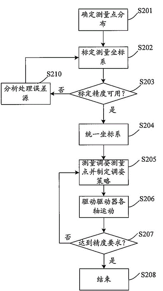
The invention provides a method for docking an object to be measured. The method comprises the steps that i, distribution of measurement points on the object to be measured is determined, and a measuring coordinate system related to a measuring spot is constructed based on the actual measurement positional values and the theoretical positional values of the measurement points; ii, the transformational relation between the measuring coordinate system and the design coordinate system of the object to be measured is constructed; iii, the position information of a pose measuring point and the position information of a drive measurement point are acquired, and the target coordinates to which an actuator corresponding to the drive measurement point is to move is determined based on the transformational relation; and iv, the actuator is driven based on the target coordinates. According to the method, measurement data and the theoretical data of a design model are comprehensively processed, and the digitization, flexibility and automation level of plane docking is improved. According to the technical scheme, the automation level of plane docking can be improved.

Description

technical field [0001] The invention belongs to the field of aircraft assembly, and in particular relates to an iGPS-based large-scale aircraft docking measurement attitude adjustment method. Background technique [0002] In the aircraft manufacturing process, the docking of most parts of the aircraft is one of the most important links. The quality of docking determines the final product performance of the aircraft, and the degree of automation of docking directly affects the efficiency of assembly and the manufacturing cycle. The real-time accurate measurement and control of most parts of the pose is the basis for automatic docking of aircraft. [0003] At present, when carrying out aircraft assembly, especially when connecting large sections such as wing and fuselage, and fuselage and fuselage, the method of fixing tooling frames and manual assembly is still mainly used. In the process of section docking, although the use of digital measurement equipment such as laser tr...

Claims


Application Information

Patent Timeline
Patent Type & Authority Applications(China)
IPC IPC(8): B23P19/10
CPCB23P19/10B23P2700/01
Inventor 孙占磊汪西宋彰桓王平景喜双周庆慧赵罡
Owner COMAC
Learn More