
Chaplet

A core support and core column technology, applied in the direction of mold box, casting molding equipment, metal processing equipment, etc., can solve the problems of increasing the difficulty of production organization, poor fusion performance, difficult operation, etc., to improve interchangeability and use efficiency, The effect of good leak-proof performance

Active Publication Date: 2016-01-06
KOCEL EQUIP
View PDF8 Cites 13 Cited by
  • Summary
  • Abstract
  • Description
  • Claims
  • Application Information

AI Technical Summary

Problems solved by technology

The current situation is that the material with higher strength has poor fusion performance, which is a physical contradiction and needs to be improved through the structural design of the core support
[0004] Most of the commonly used core supports are made of a single material, which is difficult to meet the needs of high-temperature compressive strength and good leakage prevention of castings, and high-end products have a certain limit on the number of core supports, and it is even more difficult to meet the requirements for single-material core supports.
[0005] In addition, at present, the casting core stay is mostly used in the casting box closing process, and the operator needs to nail the core support into the sand core through rivets to fix it when closing the box, which increases the time for the box closing process
And for some large castings with special structures, when it is necessary to nail the mandrel on the upper form, the operator needs to stand under the outer shape weighing more than 10 tons, and nail the mandrel upward, which is difficult to operate and has potential safety hazards
[0006] When there are many types of products or a casting needs to use core supports of various specifications and sizes, the use of core supports will have a greater impact on production organization and cost control
Excessive specifications and sizes will increase the difficulty of production organization, resulting in inconvenience and even confusion in on-site production operations, and increase production costs to a certain extent. Therefore, production organization issues also need to be considered when using core supports

Method used


Image

  • Chaplet
  • Chaplet
  • Chaplet

Examples


Embodiment Construction

[0027] Embodiments of the present invention will now be described in detail with reference to the accompanying drawings.

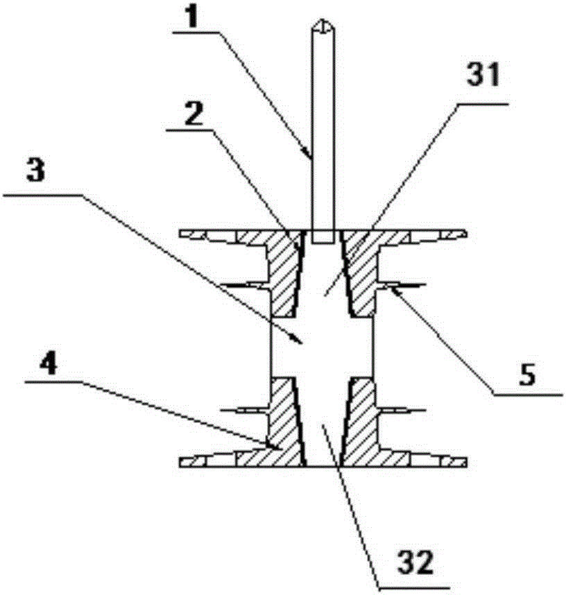
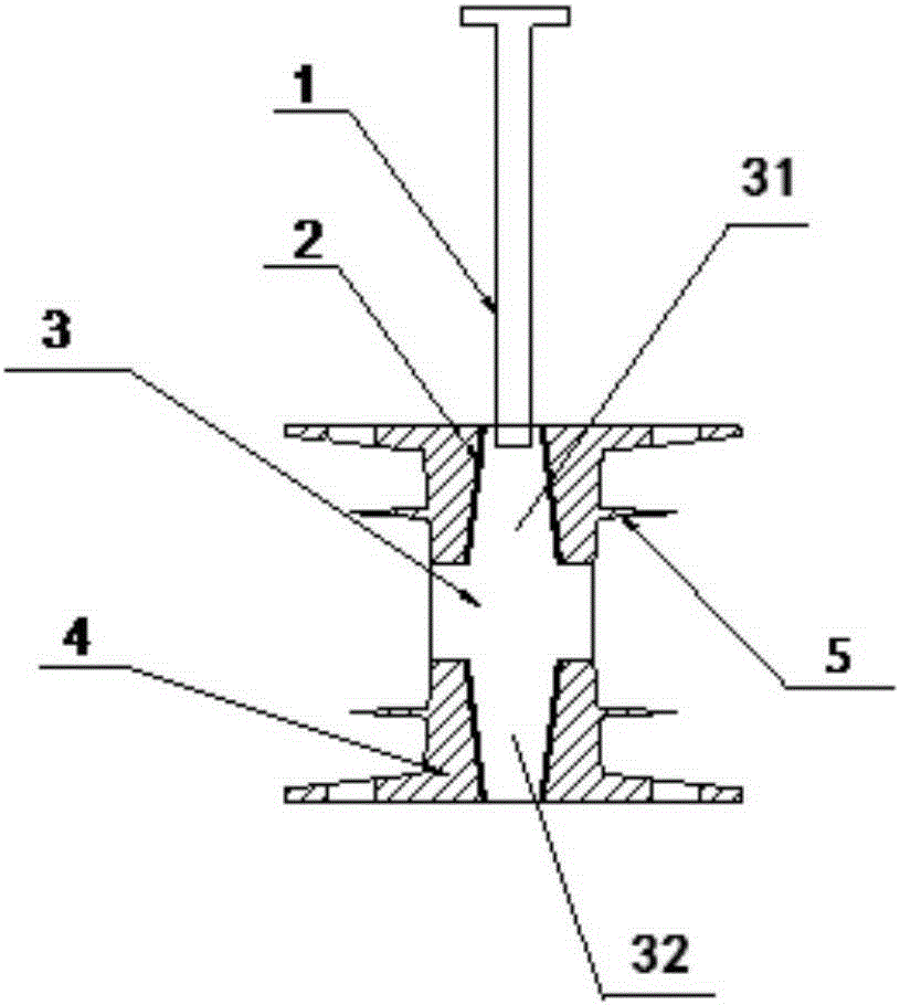
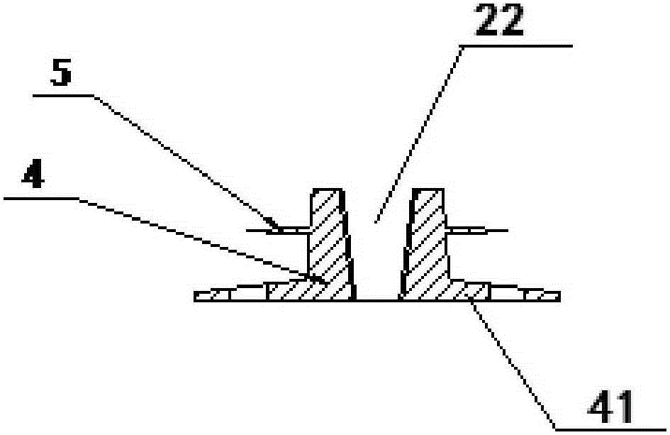
[0028] refer to figure 1 and figure 2 , The strut of the present invention includes: a core column 3 , a pair of bases 4 connected to the core column 3 and a connecting piece 1 fixedly connected to the core column 3 . The stem 3 includes a first end portion 31 and a second end portion 32 disposed opposite to each other. A pair of bases 4 are detachably connected to the first end portion 31 and the second end portion 32 respectively. Therefore, the stud of the present invention realizes the assembly of the base 4 and the stem 3, and the base 4 of the same specification can be combined with the height-adjustable stem 3, so as to solve the confusion defect that the studs of various specifications are used in the same product , Improve the interchangeability and use efficiency of the core support.

[0029] refer to Figure 1-3 , the base 4 includes a mai...


PUM


Abstract

The invention provides a chaplet which comprises a core column, a pair of bases and a connection piece. The core column comprises a first end and a second end opposite to the first end. The bases are detachably connected to the first end and the second end respectively. The connection piece is fixedly connected to the first end of the core column. The chaplet is adjustable in height and componentized. The invention further provides a casting method for embedding the chaplet in a positioning hole in a mold in the modeling step before the box combination step.

Description

technical field [0001] The present invention generally relates to the field of casting, and in particular to a stud. Background technique [0002] The foundry industry mostly adopts widely used, low-cost, and collapsible molding materials. Due to their own strength, these molding materials cannot guarantee the high-temperature dimensional stability of the cantilever structure core; or because of the product structure itself, cannot The structural design of the sand core itself is used to ensure the dimensional stability of the casting. In these cases, the core support has to be used to stabilize the core. [0003] With the continuous improvement of casting product quality requirements, casting leakage testing has become a basic indicator of casting quality requirements. In addition to high supporting strength, the core support must also have a good ability to fuse with the casting body. The current situation is that materials with higher strength have poor fusion propertie...

Claims


Application Information

Patent Timeline
Patent Type & Authority Applications(China)
IPC IPC(8): B22C21/14
Inventor 于苏杭
Owner KOCEL EQUIP
Learn More