Uniformity testing system and methodology for utilizing the same

A test system, uniformity technology, used in wheel testing, automotive tire testing, optical testing for flaws/defects, etc., which can solve problems such as large capital investment and human supervision

Inactive Publication Date: 2015-12-30
ANDROID INDS OF MICHIGAN
View PDF6 Cites 8 Cited by
  • Summary
  • Abstract
  • Description
  • Claims
  • Application Information

AI Technical Summary

Problems solved by technology

Typically, traditional methods of implementing these st...

Method used


Image

  • Uniformity testing system and methodology for utilizing the same
  • Uniformity testing system and methodology for utilizing the same
  • Uniformity testing system and methodology for utilizing the same

Examples


Embodiment Construction

[0051] Before describing embodiments of the invention, refer to Figures 4A-4D , which illustrates an exemplary tire T. Further, in describing the embodiments of the present invention, "upper", "lower", "left", "right", and "side" of the tire T may be referred to. Although such terms may be used to describe specific portions or aspects of the tire T, such terms may be employed with respect to the orientation of the mechanism for supporting / engaging the tire T (the implement rotating device 14). Accordingly, the above terms should not be used to limit the scope of the present invention, but are used herein for exemplary purposes of describing embodiments of the present invention.

[0052] In one embodiment, the tire T includes an upper sidewall surface T SU (For example, see Figure 4A ), the lower side wall surface T SL (For example, see Figure 4D ) and the upper side wall surface T SU with lower sidewall surface T SL Combined tread T T (For example, see Figures 4B-...


PUM


Abstract

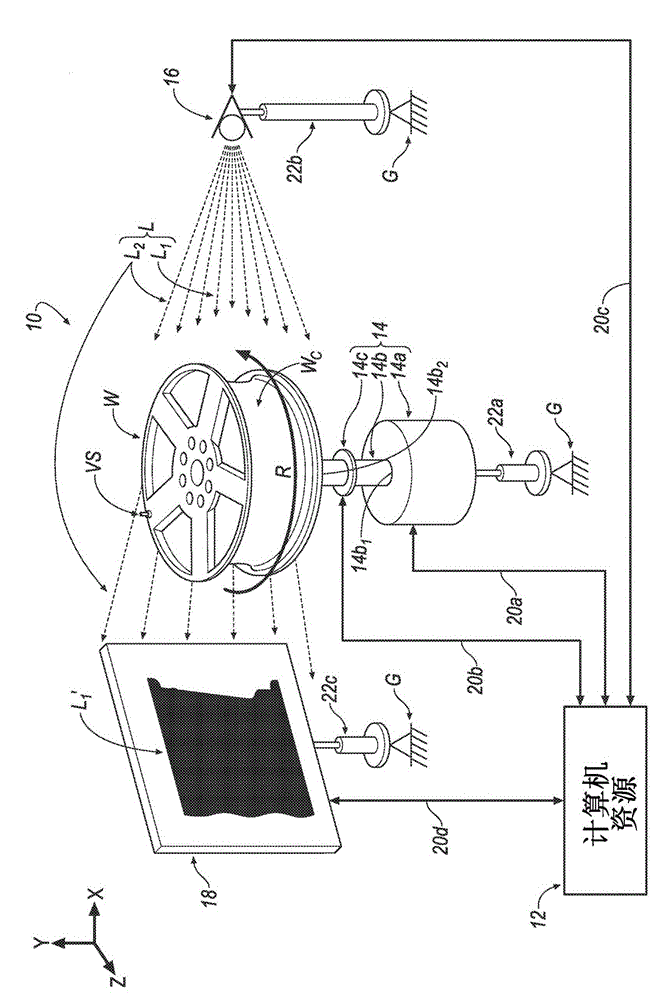
A system (10) for testing an implement (W, T, TWNI, TWI) is disclosed. The system (10) includes: a computing resource (12), an implement rotating device (14), a light emitting device (16) and a light receiving device (18). The implement rotating device (14) rotatably supports the implement (W, T, TWNI, TWI). The implement rotating device (14) is communicatively-coupled to the computing resource (12). The light emitting device (16) is communicatively-coupled to the computing resource (12). The light receiving device (18) is communicatively-coupled to the computing resource (12). The implement rotating device (14) and the implement (W, T, TWNI, TWI) are arranged between the light emitting device (16) and the light receiving device (18). The light emitting device (16) and the light receiving device (18) are substantially linearly-aligned with the implement rotating device (14) and the implement (W, T, TWNI, TWI) such that upon activating the light emitting device (16), light (L) that is emitted by the light emitting device (16) is directed toward both of the implement (W, T, TWNi, TWi) and the light receiving device (18) whereby the light receiving device (18) captures an image corresponding to a portion (L2) of the light (L) emitted by the light emitting device (16) and a shadow (L1') formed by at least a portion of the implement (W, T, TWNI, TWI). The shadow (L1') corresponds to another portion (L1) of the light (L) that is not received by the light receiving device (18). The light receiving device (18) communicates the captured image to the computing resource (12) for determining uniformity or a lack of uniformity of the implement (W, T, TWNI, TWI). A method (100) for utilizing the system (10) is also disclosed. A computer program product is also disclosed.

Description

[0001] Cross References to Related Applications [0002] This US patent application claims priority to US Provisional Application 61 / 823,261, filed May 14, 2013, the disclosure of which is considered a part of this Provisional Application and is incorporated herein by reference in its entirety. technical field [0003] The invention relates to a uniformity testing system and its utilization method. Background technique [0004] There are several steps known in the art to install a tire-wheel assembly. Typically, traditional methods of implementing these steps require significant capital investment and human oversight. The present invention overcomes the disadvantages associated with the prior art by proposing a system and method that is simply associated with one or more steps of assembling a tire-hub assembly. Contents of the invention [0005] One aspect of the present invention provides an object testing system. The system may include computer resources, object rotat...

Claims


Application Information

Patent Timeline
IPC IPC(8): G01B11/24G01B11/30G01N21/88G01N21/952G01M17/013G01M17/02
CPCG01N21/952G01N21/8851G01N2021/8887G01N21/84
Inventor L·J·劳森D·G·斯特拉伊蒂夫B·A·克拉克R·R·尼亚齐
Owner ANDROID INDS OF MICHIGAN
Why Eureka
Try Eureka