
A detection device and method for the main board of electric energy meter based on electromagnet drive

A detection method and electromagnet technology, applied in the direction of measuring device, electronic circuit testing, measuring electricity, etc., can solve the problems of the device occupying a large space, being easily injured, and the operator cannot directly observe the liquid crystal display and LED indicator display, etc. Easy installation and small footprint

Active Publication Date: 2018-03-13
北方智能装备有限公司
View PDF9 Cites 0 Cited by
  • Summary
  • Abstract
  • Description
  • Claims
  • Application Information

AI Technical Summary

Problems solved by technology

[0003] The current detection device for the main board of the electric energy meter adopts the air valve control method, which has obvious disadvantages: when the detection device is installed, a special air guide tube needs to be installed and used with an air pump, which is inconvenient to install and move; The noise is loud; the working method of the air valve is to press from top to bottom, and the pressure is relatively large. Once the worker makes a mistake in operation or the hair is clamped, it is very easy to get injured or get an electric shock; the device needs to be controlled manually, and the detection device usually has a "valve start button". " and "air valve close button", after the operator places the main board of the electric energy meter, the device cannot automatically start the detection, and the detection must be started by manually pressing the start button; the air valve drives the receiving plate for a long distance, and the air valve movement Slow speed and low efficiency; usually the cylinder volume is large, and the device takes up a lot of space; the main board of the electric energy meter usually places the liquid crystal downward, and the operator cannot directly observe the liquid crystal display and the display of the LED indicator light

Method used


Image

  • A detection device and method for the main board of electric energy meter based on electromagnet drive
  • A detection device and method for the main board of electric energy meter based on electromagnet drive
  • A detection device and method for the main board of electric energy meter based on electromagnet drive

Examples


Embodiment Construction

[0023] The present invention will be described in detail below in conjunction with the embodiments shown in the accompanying drawings.

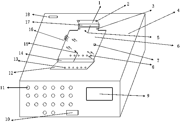
[0024] Such as figure 1 with figure 2 As shown, the device of the present invention includes main parts such as a flip plate, a permanent magnet, an electromagnet, and a rotating column, and also includes a front portion with a micropower meter display window 9 opening, an LED indicator window 10 opening, and an LED indicator light 11 Open 4-housing; there is a slot 6 for the main board of the electric energy meter on the upper part of the shell, and the main board of the electric energy meter to be tested can be placed in the slot for the main board of the electric energy meter; Installed at position 3 of the upper electromagnet column, 6 electromagnet columns are installed at position 8 of the lower electromagnet column; the upper and lower ends of the placement slot are respectively installed with a rotating column 14 and a detection pro...


PUM


Abstract

An electromagnet-driven detection device and method for a main board of an electric energy meter relates to a detection device and method for a main board of an electric energy meter. Iron column, two electromagnet columns are installed at the position of the upper electromagnet column, and 6 electromagnet columns are installed at the position of the lower electromagnet column; the upper and lower ends of the placement slot are respectively installed with a rotating column and a detection probe; the rotating column is fixed with the upper flap Connection, the rotating column is fixedly connected with the lower flap; the upper flap is installed with the upper flap permanent magnet column, and the lower flap is installed with the lower flap permanent magnet column; the retractable detection probe is installed in the placement slot; the upper part of the housing is installed with a miniature printer. The main board of the electric energy meter of the present invention automatically starts detection, and automatically prints the detection results after the detection is completed. During the test process, the pulse indicator light, the state of the trip light, and the detection operations such as the button for opening the cover can be directly observed.

Description

technical field [0001] The invention relates to a detection device and method for a main board of an electric meter, in particular to a detection device and a method for a main board of an electric energy meter which drives an electromagnet through an electric current. Background technique [0002] In recent years, the construction of my country's smart grid has been in full swing, and single-phase smart meters have been widely used across the country. In 2015, the number of the first bidding of the State Grid Corporation alone reached 36.19 million smart meters. Faced with such a huge number of orders, many manufacturers have not been able to supply goods in time, and the quality of electric energy meters cannot be guaranteed. In the production process, the most problematic part of the energy meter is the main board of the electric energy meter. Almost all the main components of the electric energy meter are integrated on the main board of the electric energy meter. The au...

Claims


Application Information

Patent Timeline
Patent Type & Authority Patents(China)
IPC IPC(8): G01R31/28G01R31/02
Inventor 张俊哲耿春丽高新袁滨成冯春华孔德钰杨哲孙维鸿
Owner 北方智能装备有限公司
Learn More