A method for calculating the recovery voltage of complex wavefront sensing adaptive optics system

A technology of adaptive optics and wavefront restoration, applied in the field of adaptive optics, can solve problems such as underdetermined correction voltage, and achieve the effects of preventing high-order aberrations, improving stability, and improving closed-loop accuracy

Active Publication Date: 2018-04-03
INST OF OPTICS & ELECTRONICS - CHINESE ACAD OF SCI
View PDF5 Cites 0 Cited by
  • Summary
  • Abstract
  • Description
  • Claims
  • Application Information

AI Technical Summary

Problems solved by technology

[0005] The technical problem to be solved by the present invention is: to overcome the deficiencies of the prior art, and propose a method for calculating the recovery voltage of the complex wavefront sensing adaptive optical system, which can overcome the low-order sensor in the complex wavefront sensing adaptive optical system The problem of underdetermined correction voltage caused by the mismatch between the number of sub-apertures and the number of deformable mirror drivers can effectively prevent the wavefront corrector from producing high-order aberrations that cannot be detected by low-order wavefront sensors, and improve system stability and closed-loop accuracy

Method used


Image

  • A method for calculating the recovery voltage of complex wavefront sensing adaptive optics system
  • A method for calculating the recovery voltage of complex wavefront sensing adaptive optics system
  • A method for calculating the recovery voltage of complex wavefront sensing adaptive optics system

Examples


Embodiment Construction

[0020] The present invention will be further described below in conjunction with the accompanying drawings and specific embodiments.

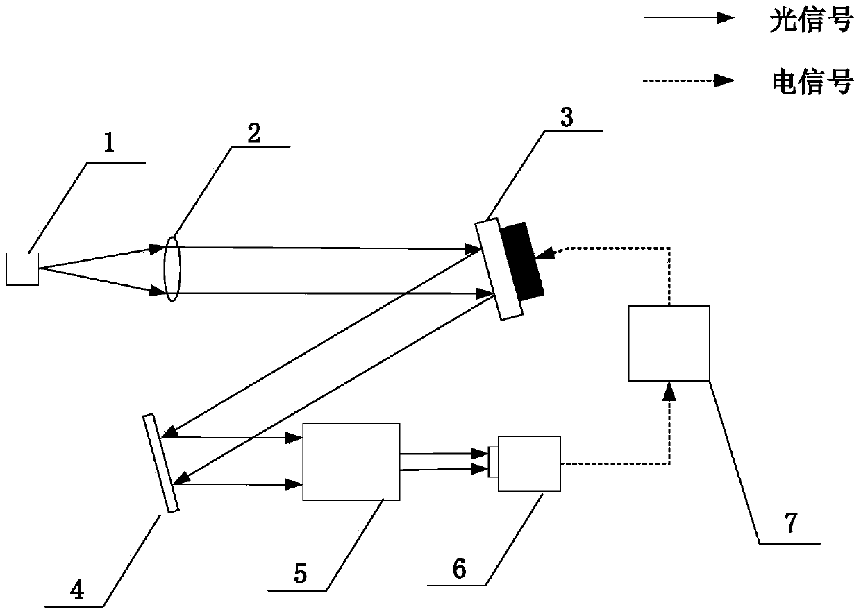
[0021] A method for calculating the recovery voltage of a composite wavefront sensing adaptive optics system, when selecting a high-order wavefront sensor and a wavefront corrector to form a high-order adaptive optics system, using the direct slope wavefront restoration matrix R 0 Multiplied by the wavefront slope s measured by the higher order wavefront sensor 0 The restoration voltage v is obtained; when a low-order wavefront sensor and a wavefront corrector are selected to form a low-order adaptive optics system, the calculation of the restoration voltage v has the following steps:

[0022] Step (1), using the mode reconstruction matrix W of the low-order adaptive optics system 1 Multiplied by the wavefront slope error s measured by the low-order wavefront sensor 1 Get the wavefront error coefficient a 1 ;

[0023] Step (2), using the mo...


PUM


Abstract

The present invention provides a method for calculating the recovery voltage of a composite wavefront sensing adaptive optical system. When a high-order wavefront sensor and a wavefront corrector are selected to form a high-order adaptive optical system, the direct slope wavefront restoration matrix R0 is used to multiply the high-order wavefront The wavefront slope s0 measured by the front sensor is used to obtain the restored voltage v; when a low-order wavefront sensor and a wavefront corrector are selected to form a low-order adaptive optics system, the calculation of the restored voltage v has the following steps: (1) Using the low-order self-adaptive optics system The mode reconstruction matrix W1 of the adaptive optics system is multiplied by the wavefront slope error s1 measured by the low-order wavefront sensor to obtain the wavefront error coefficient a1; (2) the mode response matrix M0 of the high-order adaptive optics system is multiplied by a1 to obtain The corresponding wavefront slope s2 of the high-order wavefront sensor under the aberration of the mode coefficient a1; (3) The restored voltage v is obtained by multiplying the wavefront slope s2 by the direct slope wavefront restoration matrix R0. The invention can effectively prevent the wavefront corrector from producing high-order aberrations that cannot be detected by low-order wavefront sensors, and improve the stability and closed-loop accuracy of the system.

Description

technical field [0001] The invention relates to the technical field of adaptive optics, in particular to a method for calculating the recovery voltage of a composite wavefront sensing adaptive optics system. Background technique [0002] The wavefront correction capability of an adaptive optics system is affected by the measurement error of the wavefront sensor. Since the wavefront distortion of atmospheric turbulence is widely distributed in the spatial frequency domain, the higher the spatial sampling rate of the wavefront sensor is, the closer the reconstructed wavefront distortion is to reality. However, when observing extended targets, affected by the contrast of beacons (such as sunspots or rice grains), the higher the spatial sampling rate, the smaller the sub-aperture, the lower the contrast of the image in the sub-aperture, and the greater the measurement error of the wavefront slope. When observing a point source target, the higher the spatial sampling rate, the w...

Claims


Application Information

Patent Timeline
Patent Type & Authority Patents(China)
IPC IPC(8): G01J9/00G01J1/00G02B26/06G02B27/00
Inventor 饶长辉郭友明张兰强饶学军朱磊鲍华
Owner INST OF OPTICS & ELECTRONICS - CHINESE ACAD OF SCI
Why Eureka
Try Eureka