
Sleeve-type yarn unwinding roller

A yarn roller and sleeve technology, which is applied in the field of yarn release rollers, can solve problems such as easy accumulation of dust, and achieve the effects of preventing dirt accumulation, saving costs, and improving efficacy

Inactive Publication Date: 2015-12-30
CHANGZHOU YINGHUANGGUAN IMPORTS & EXPORTS
View PDF6 Cites 0 Cited by
  • Summary
  • Abstract
  • Description
  • Claims
  • Application Information

AI Technical Summary

Problems solved by technology

[0003] In order to overcome the deficiency that the existing yarn-releasing rollers are easy to accumulate dust, the invention provides a sleeve-type yarn-releasing roller

Method used


Image

  • Sleeve-type yarn unwinding roller

Examples


Embodiment Construction

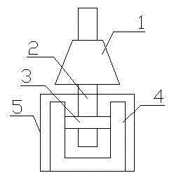
[0009] Such as figure 1 It is a schematic diagram of the structure of the present invention. The sleeve-type yarn unwinding roller includes a roller 1, a roller shaft 2, a bearing 3 and a fixed seat 4. The roller shaft 2 is placed in the roller 1, and the bottom end of the roller shaft 2 is placed in the bearing 3. ring, the fixed seat 4 is fixedly connected with the outer ring of the bearing 3, the fixed seat 4 is sleeved in the glass cylinder 5, and the roller shaft 2 passes through the glass cylinder 5.

[0010] When the glass tube 5 is sleeved on the fixed seat 4, the external dirt is isolated on the glass tube 5, and the glass tube 5 can prevent being corroded by the dirt and prolong the service life. Internal dirt accumulation saves cost and improves efficacy.


PUM


Abstract

The invention relates to a yarn unwinding roller, in particular to a sleeve-type yarn unwinding roller which comprises a roller barrel, a roller shaft, a bearing and a fixing seat. The roller shaft is arranged in the roller barrel, the bottom end of the roller shaft is arranged in an inner ring of the bearing, the fixing seat is fixedly connected with an outer ring of the bearing and sleeved with a glass barrel, and the roller shaft penetrates through the glass barrel. According to the yarn unwinding roller, dirt accumulation in the fixing seat can be prevented, the cost is saved, and the effects are improved.

Description

technical field [0001] The invention relates to a yarn-releasing roller, especially a sleeve-type yarn-releasing roller. Background technique [0002] With the development of the economy, people's demand for textile products is increasing. The improvement of the equipment used for textile has greatly promoted the efficiency of textile production. In textile production, unwinding yarn from the bobbin is an essential part of production. In the previous yarn unwinding equipment, the bottom of the fixing seat would affect the rotation of the roller shaft due to the accumulation of dirt. Contents of the invention [0003] In order to overcome the disadvantage that the existing yarn letting rollers are easy to accumulate dust, the invention provides a sleeve-type yarn letting roller. [0004] The technical scheme adopted by the present invention to solve the technical problem is: stacking type yarn unwinding roller, including roller, roller shaft, bearing and fixing seat, the ...

Claims


Application Information

Patent Timeline
IPC IPC(8): B65H75/10B65H75/18
Inventor 费春寅
Owner CHANGZHOU YINGHUANGGUAN IMPORTS & EXPORTS
Learn More