
Multi-group multi-barrel molecular sieve runner alternate intermittent cycle dehumidification dryer

A molecular sieve, circulating technology, used in non-progressive dryers, dryers, drying and other directions, can solve problems such as energy consumption, excessive cooling water, waste of residual heat, etc. Low requirements and the effect of reducing installation space

Active Publication Date: 2017-08-25
苏州瑞倍成机械设备有限公司
View PDF5 Cites 0 Cited by
  • Summary
  • Abstract
  • Description
  • Claims
  • Application Information

AI Technical Summary

Problems solved by technology

[0007] Therefore, the ceramic honeycomb structure is not suitable for the treatment of materials requiring stable low dew point
[0008] 2. The regeneration temperature is not high, and the regeneration is not sufficient
[0009] 3. Severe cross wind inside the honeycomb runner, insufficient regeneration of moisture absorbent
[0010] 4. The honeycomb is porous, the regeneration wind is easy to penetrate, and the heat loss is large
[0012] 1. The air in the working circuit of the machine can reach a lower dew point, but the dew point is not stable and fluctuates greatly, so it is not suitable for occasions that require a stable dew point
[0013] 2. The pipeline is complex, and the machine work requires complex control logic
[0014] 3. The residual heat generated by the regeneration of the granular molecular sieve desiccant will be wasted; in addition, more cooling water is required to consume energy during drying; the energy is greatly lost during the transfer of the processed materials
4. The weight of the machine is large and the space requirement is large, so it is not suitable for direct connection with the plasticizing equipment below

Method used


Image

  • Multi-group multi-barrel molecular sieve runner alternate intermittent cycle dehumidification dryer
  • Multi-group multi-barrel molecular sieve runner alternate intermittent cycle dehumidification dryer
  • Multi-group multi-barrel molecular sieve runner alternate intermittent cycle dehumidification dryer

Examples


Embodiment Construction

[0071] The present invention will be further described in detail below in conjunction with the accompanying drawings and specific preferred embodiments.

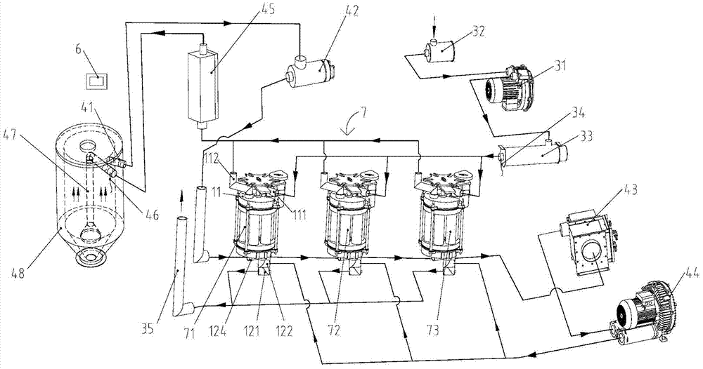
[0072] Such as figure 1 As shown, a multi-group multi-barrel molecular sieve runner alternate intermittent cycle dehumidification dryer is used for drying and dehumidification of plastic particles in the drying hopper 48, which includes at least two multi-barrel dehumidification runner groups 7 connected in parallel, preferably for example for 3 pcs.

[0073] The three multi-barrel dehumidification runners 7 are respectively the first multi-barrel dehumidification runner 71, the second multi-barrel dehumidification runner 72 and the third multi-barrel dehumidification runner 73. The three multi-barrel dehumidification runners 7 Alternate interval cycles.

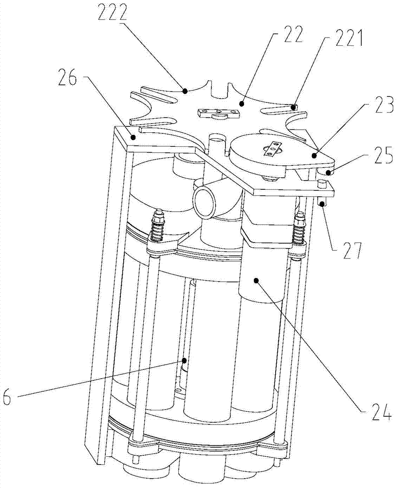
[0074] Each multi-barrel dehumidification runner group 7 includes a multi-barrel molecular sieve runner 1, an intermittent drive mechanism 2, a fan 31, a first filter 32...


PUM


Abstract

The invention discloses a multi-group multi-barrel molecular sieve runner alternate intermittent cycle type dehumidification dryer, which comprises at least two multi-barrel dehumidification runner groups connected in parallel, and each multi-barrel dehumidification runner group includes a multi-barrel molecular sieve runner and intermittent drives. The multi-barrel molecular sieve runner includes a top cover, a bottom cover and at least three dehumidification barrels, and each dehumidification barrel is filled with granular molecular sieve desiccant; the intermittent drive mechanism includes a rotating shaft capable of intermittent rotation, and the dehumidification barrels are evenly arranged on the outer periphery of the rotating shaft, and Fixed connection with the shaft. After adopting the above-mentioned structure, the multi-barrel dehumidification rotor group alternates and intermittently circulates, and the multiple dehumidification barrels in each multi-barrel dehumidification rotor group can be driven by the rotating shaft to intermittently perform regeneration-cooling-treatment cycle cycle Working, the air in the working circuit can reach a lower dew point, and the dew point is stable, the fluctuation range is small, and the range can be adjusted. At the same time, the granular molecular sieve desiccant has sufficient regeneration, high energy utilization rate, and small equipment footprint.

Description

technical field [0001] The invention relates to a dehumidification drier, in particular to a dehumidification drier with multiple sets of multi-barrel molecular sieve runners alternately and intermittently circulating. Background technique [0002] Plastic particles Undried plastic particles usually contain a certain amount of moisture, especially engineering plastic particles are particularly easy to absorb moisture. If the moisture content of the material is not controlled within a certain range, it will have a great impact on the subsequent injection molding, and there will be fireworks on the surface of the molded part. Bubble strips, silver wires, pores, and reduced mechanical properties. Therefore, in the early stage of plastic molding, a dehumidification dryer is generally used to form a dry air flow with a certain temperature and a low dew point to remove the moisture contained in the plastic particles. The moisture is discharged into the air under the state, and th...

Claims


Application Information

Patent Timeline
Patent Type & Authority Patents(China)
IPC IPC(8): B29B13/06F26B11/08
CPCB29B9/16
Inventor 吴莲
Owner 苏州瑞倍成机械设备有限公司
Learn More