A stator magnetic steel bonding mold and bonding method thereof

A magnetic steel and bonding technology, which is applied in the manufacture of stator/rotor bodies, etc., can solve problems such as being unsuitable for mass motor production, the quality of the motor cannot be guaranteed, and the bonding firmness of magnetic steel is affected, so as to achieve good processing efficiency and Processing quality, elimination of easy falling off, convenient processing effect

Active Publication Date: 2017-12-22
GUIZHOU AEROSPACE LINQUAN MOTOR CO LTD
View PDF4 Cites 0 Cited by
  • Summary
  • Abstract
  • Description
  • Claims
  • Application Information

AI Technical Summary

Problems solved by technology

However, the shortcomings in the actual production process are: because the built-in positioning is adopted, the magnetic steel is placed in the positioning mandrel, and the magnetic steel is parallel to the inner surface of the casing due to the suction force of the magnetic steel; The steel surface is coated with adhesive, and the adhesive on the surface will be hung up by the end of the casing, resulting in a reduction in the actual use of adhesive, which seriously affects the bonding firmness of the magnetic steel; moreover, due to the suction of the magnetic steel, When pressing into the casing, the resistance is relatively large, and a large force is required to press the magnetic steel in; the production efficiency is low, the reliability of the bonding is poor, and the bonding force is not high, and the magnetic steel is prone to fall off, causing the magnetic steel to fall off. The quality of the motor cannot be guaranteed, and it is not suitable for mass production of motors

Method used


Image

  • A stator magnetic steel bonding mold and bonding method thereof
  • A stator magnetic steel bonding mold and bonding method thereof
  • A stator magnetic steel bonding mold and bonding method thereof

Examples


Embodiment Construction

[0022] The technical solution of the present invention is further described below in conjunction with the accompanying drawings of the embodiments, but the scope of protection is not limited to the description.

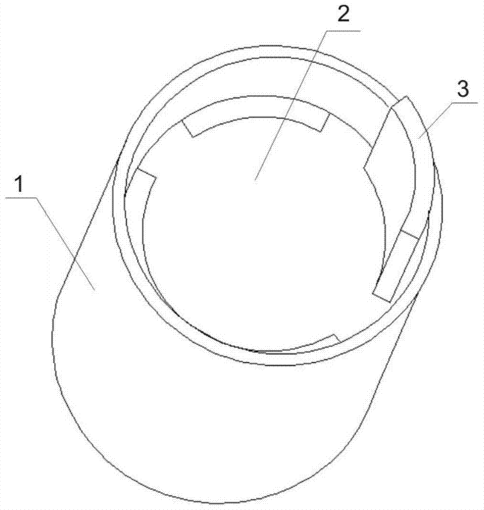
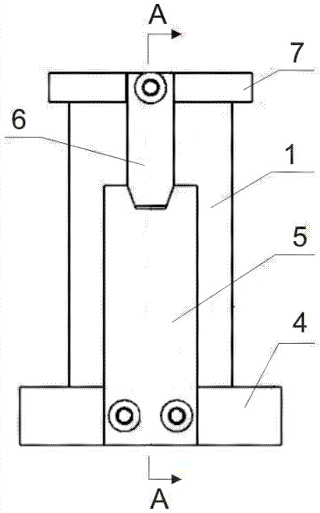
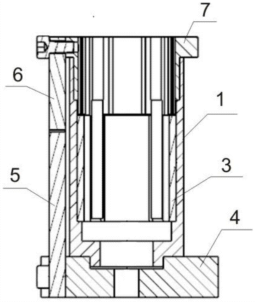
[0023] like Figure 2 to Figure 4 As shown, a stator magnetic steel bonding mold according to the present invention includes a base 4, a casing 1, a positioning sleeve 7, a lower positioning plate 5 and an upper positioning plate 6, and the casing 1 is arranged in the base 4, The positioning sleeve 7 is placed inside the casing 1, the lower end of the lower positioning plate 5 is fixed on the base 4 by screws, the upper end is connected with the lower end of the upper positioning plate 6, and the upper end of the upper positioning plate 6 is fixed on the positioning sleeve 7 by screws. The technical solution uses the external lower positioning plate 5 and the upper positioning plate 6 to position the positioning sleeve 7, the positioning sleeve 7 is convenient and qui...


PUM


Abstract

The invention discloses a stator magnetic steel bonding mold and a bonding method thereof, comprising a base, a casing, a positioning sleeve, a lower positioning plate and an upper positioning plate, the casing is arranged in the base, and the positioning sleeve is placed in the casing Inside, the lower end of the lower positioning plate is fixed on the base by screws, the upper end is connected with the lower end of the upper positioning plate, and the upper end of the upper positioning plate is fixed on the positioning sleeve by screws, and the positioning sleeve is composed of the head and the Composed of inserting sections, fan-shaped positioning holes are evenly arranged inside the head, and bosses are arranged on the fan-shaped positioning holes; the bonding method includes several steps of installing the casing, installing the positioning sleeve and bonding the magnetic steel. In the present invention, when the magnetic steel is bonded, the surface of the magnetic steel and the surface of the casing are in an inclined state, and the magnetic steel and the casing are in line contact, which reduces frictional resistance; prevents the adhesive on the surface of the magnetic steel from being scraped off by the end face of the casing, ensuring The balance of the bonding force of the magnetic steel improves the bonding firmness and prevents the magnetic steel from falling off.

Description

technical field [0001] The invention belongs to the technical field of motor manufacturing, and relates to the bonding of stator magnetic steel in the motor manufacturing industry, in particular to a stator magnetic steel bonding mold and a bonding method thereof. Background technique [0002] The bonding of the existing motor stator magnetic steel mainly adopts the built-in mandrel positioning method. Its tooling structure is as figure 1 As shown, it is mainly composed of a casing 1 and a positioning mandrel 2. The way of using this tool for positioning and connecting magnets is widely used in the production of motors. The bonding process is as follows: (1) Put the positioning mandrel 2 into the casing 1; (2) Put the hand-held magnetic steel 3 into the positioning hole of the positioning mandrel 2; (3) Press the magnetic steel 3 vertically by pressure. into the bottom of the case 1. The bonding method of the magnetic steel has the advantages of convenience, simplicity, ...

Claims


Application Information

Patent Timeline
Patent Type & Authority Patents(China)
IPC IPC(8): H02K15/03
Inventor 刘敬东虞静
Owner GUIZHOU AEROSPACE LINQUAN MOTOR CO LTD
Why Eureka
Try Eureka