Switch cabinet forced ventilation dehumidification system

A forced ventilation and switchgear technology, applied in the cooling/ventilation of substation/switchgear, substation/switch layout details, electrical components, etc. Achieve economical and cheap system transformation, ensure normal operation, and achieve obvious effects of dehumidification

Active Publication Date: 2017-10-24
STATE GRID TIANJIN ELECTRIC POWER +1
View PDF3 Cites 0 Cited by
  • Summary
  • Abstract
  • Description
  • Claims
  • Application Information

AI Technical Summary

Problems solved by technology

The increase of air humidity in the busbar room will intensify the condensation phenomenon in the busbar room, which will easily cause working failure and equipment damage in the busbar room

Method used


Image

  • Switch cabinet forced ventilation dehumidification system
  • Switch cabinet forced ventilation dehumidification system
  • Switch cabinet forced ventilation dehumidification system

Examples


Embodiment Construction

[0022] The following describes the embodiments of the present invention in detail with reference to the accompanying drawings; it should be noted that this embodiment is narrative and not restrictive, and the protection scope of the present invention cannot be limited by this.

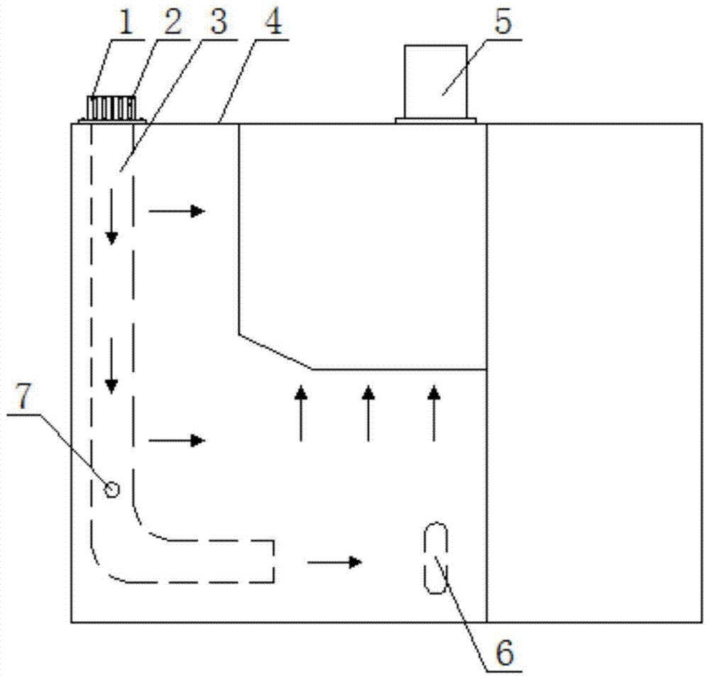
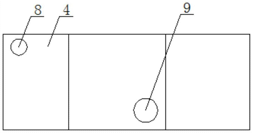
[0023] A forced ventilation and dehumidification system for a switch cabinet, including a cabinet body 4, a tuyere 8, a ventilation duct 3 and a fan system. A tuyere is made on the top plate of the cabinet body. The tuyere is a circular opening with a diameter of 100mm to ensure ventilation. The need for traffic. A square metal cap 1 is set above the air outlet. The four sides of the square metal cap are provided with rectangular vertical strip holes 2. Each hole is 100mm long and 1mm wide, and there are fixing bolts and holes on the edge. The square metal cap covers the circle. Above the opening, it is fixed to the top plate by bolts.

[0024] The air outlet is connected to a ventilation duct located in t...


PUM


Abstract

The invention relates to a forced ventilation dehumidifying system for a switch cabinet, and the system comprises a cabinet body. A top plate of the cabinet body is provided with a wind gap, and the wind gap is communicated with a ventilation pipeline located in the cabinet body. The ventilation pipeline is formed by the connection of a vertical segment and a horizontal segment, wherein the horizontal segment is located at the lower part of the cabinet body. The top plate of the cabinet body is also provided with a blower fan port, and the blower fan port is provided with a blower fan communicated with the interior of the cabinet body. The interior of the cabinet body is provided with a hygrothermograph, and the hygrothermograph is electrically connected with a logic control unit, wherein the logic control unit is electrically connected with the blower fan. The system eliminates wet air in the switch cabinet. The top of the cabinet is provided with a vent hole and the interior of the cabinet is additionally provided with an air channel. The top of the cabinet is additionally provided with the blower fan, thereby forming a forced ventilation dehumidifying line. The system can enable the wet air in the cabinet to be discharged from the cabinet body, avoids a condensation phenomenon, finally protects equipment in the switch cabinet from being damaged, and guarantees the normal operation of power equipment.

Description

Technical field [0001] The invention relates to switch cabinet dehumidification technology in the field of power technology, in particular to a switch cabinet forced ventilation and dehumidification system. Background technique [0002] The root cause of condensation in the switchgear is that the moisture in the bottom cable trench enters the cable room from the gap. As time accumulates, the air humidity in the cable room gradually increases. It enters other compartments through the partition openings and gaps, making the compartment easier Condensation occurs. The existing anti-condensation methods often install heaters in the cable room and the circuit breaker room. Although this method helps to slow down the condensation phenomenon in the cable room and the circuit breaker room, when the heater is working, it makes the cable room and the circuit breaker room As the air temperature rises, due to the effect of natural convection, the moist air at the bottom converges into the b...

Claims


Application Information

Patent Timeline
Patent Type & Authority Patents(China)
IPC IPC(8): H02B1/56H02B1/28
CPCH02B1/28H02B1/565
Inventor 陈荣张利满玉岩唐庆华张弛王小朋张黎明李松原何金宋晓博
Owner STATE GRID TIANJIN ELECTRIC POWER
Why Eureka
Try Eureka