
Embedded capacitive touch display panel

A capacitive touch and display panel technology, which is applied in the input/output process of electrical digital data processing, instruments, and data processing, etc., can solve the problem of poor touch sensitivity, increased plastic frame size, and large touch circuit resistance. problem, to achieve better touch sensitivity, reduced thickness, and reduced resistance

Active Publication Date: 2018-04-20
KUSN INFOVISION OPTOELECTRONICS
View PDF5 Cites 0 Cited by
  • Summary
  • Abstract
  • Description
  • Claims
  • Application Information

AI Technical Summary

Problems solved by technology

Considering the aperture ratio, the touch driving electrodes and touch sensing electrodes are usually made of transparent conductive materials (such as ITO). Due to the high impedance of the transparent conductive materials, the resistance of the touch circuit is relatively large, and the touch driving electrodes and touch sensing electrodes The switching between electrodes and common electrodes is not fast enough, resulting in poor touch sensitivity
In addition, the touch sensing electrodes are usually fabricated above or below the color filter (CF) substrate. Since the substrate of the color filter substrate is thin, the yield of the touch sensing electrodes on the substrate is low. Fragments are very easy to occur, and when the touch sensing electrodes are made under the color filter substrate, the signal of the touch sensing electrodes needs to be conducted to the Array substrate through the gold ball in the plastic frame, which increases the size of the plastic frame. Increased the overall thickness of the display panel and the size of the white border

Method used


Image

  • Embedded capacitive touch display panel
  • Embedded capacitive touch display panel
  • Embedded capacitive touch display panel

Examples


Embodiment Construction

[0021] In order to make the purpose, technical solution and advantages of the present invention clearer, the embodiments of the present invention will be further described in detail below in conjunction with the accompanying drawings.

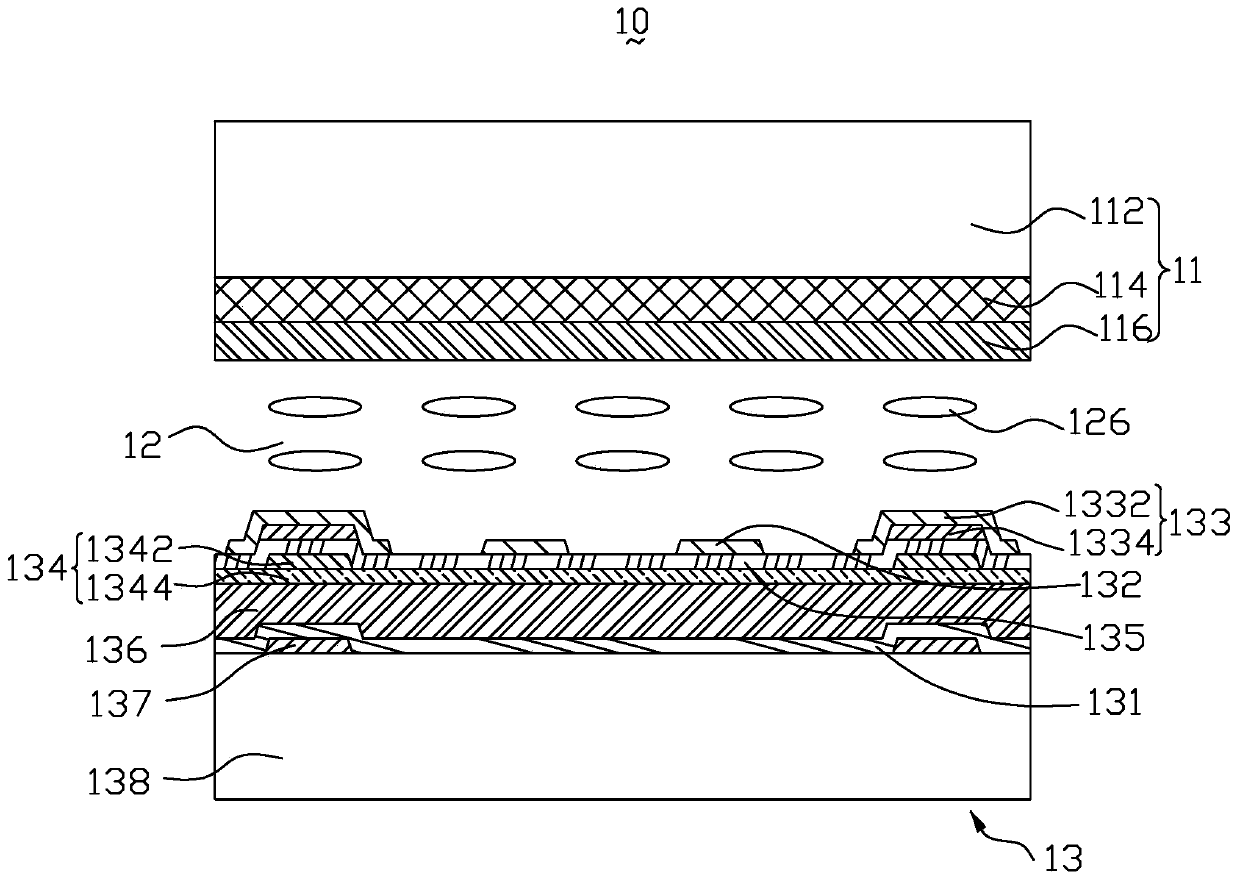
[0022] The orientations “up” and “down” mentioned in the description of the present invention are only used to represent the relative orientation relationship; for the drawings in this specification, the top of the embedded capacitive touch display panel 10 is closer to the viewer, The lower part is further away from the viewer.

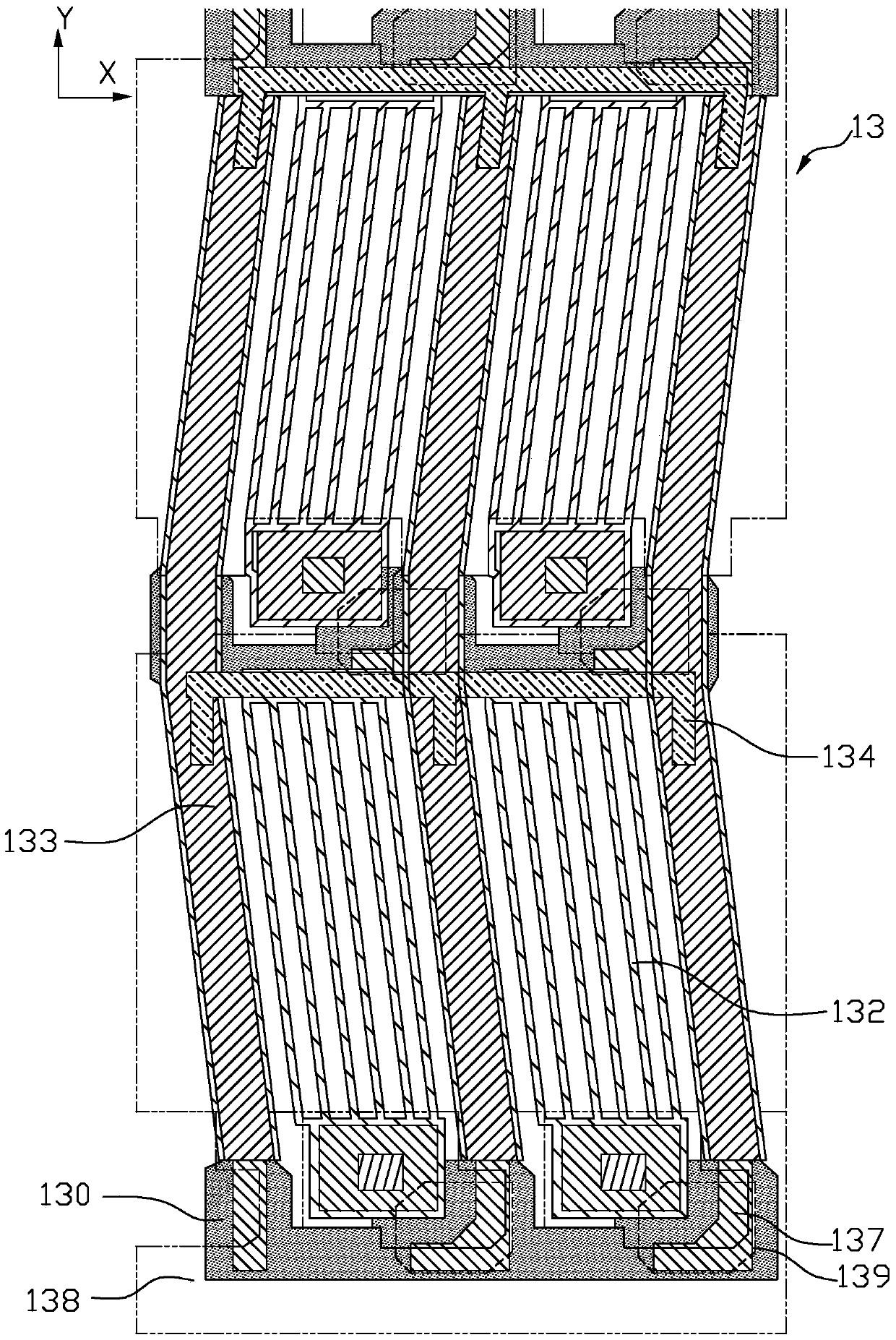
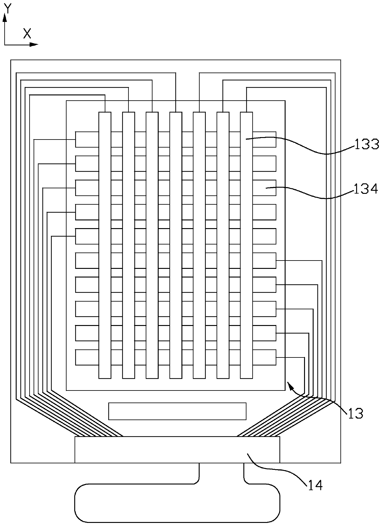
[0023] figure 1 is a schematic structural diagram of an in-cell capacitive touch display panel according to an embodiment of the present invention, figure 2 It is a schematic diagram of the layered structure of the array substrate and the touch electrode of the embodiment of the present invention, image 3 It is a schematic diagram of the layered structure of the touch electrode according to the embodiment of the p...


PUM


Abstract

An in-cell capacitive touch display panel, which sequentially includes a color filter substrate, a liquid crystal layer, and an array substrate from top to bottom, and the array substrate includes pixel electrodes, a first common electrode, a first insulating layer, and a second common electrode. An electrode, and a substrate, the second common electrode is arranged above the substrate, the first insulating layer is arranged above the second common electrode, and the pixel electrode and the first common electrode are arranged at intervals on the same layer And it is arranged above the first insulating layer, the first common electrode and the second common electrode are formed into strips and the extending directions are perpendicular to each other, and the in-cell capacitive touch display panel also includes a touch electrode. The control electrodes include touch sensing electrodes and touch driving electrodes, the touch sensing electrodes are shared with the first common electrodes, the touch driving electrodes are shared with the second common electrodes, the touch sensing electrodes are shared with the The touch driving electrodes all adopt a structure combining metal materials and transparent conductive materials.

Description

technical field [0001] The invention relates to the field of liquid crystal display technology, in particular to an embedded capacitive touch display panel. Background technique [0002] Currently, touch technology has been widely applied to various electronic products with display panels, such as mobile phones, computers, personal digital assistants (PDAs), and flat-screen TVs. [0003] Touch display panels (referred to as touch display panels) can be divided into resistive, capacitive, optical, acoustic, and electromagnetic types according to different sensing principles. Because capacitive touch display panels have fast response speed and sensitivity High performance, good reliability, and high durability are recognized by the industry and are more widely used. [0004] Compared with the traditional method of setting the touch display panel on the liquid crystal panel, the integrated technology research and development route mainly includes two categories: In cell and On...

Claims


Application Information

Patent Timeline
Patent Type & Authority Patents(China)
IPC IPC(8): G06F3/044
Inventor 钟德镇郑会龙
Owner KUSN INFOVISION OPTOELECTRONICS
Learn More