Magnetostriction micro displacement meter

A technology of magnetostriction and displacement meter, which is applied in the direction of using electromagnetic means, measuring devices, instruments, etc., can solve the problems that the field of micro-displacement measurement cannot be applied, and the application field is narrow, so as to improve the utilization rate of the magnetic field, improve the accuracy, and improve the magnetic induction The effect of intensity

Active Publication Date: 2015-12-23
HEBEI UNIV OF TECH
View PDF5 Cites 6 Cited by
  • Summary
  • Abstract
  • Description
  • Claims
  • Application Information

AI Technical Summary

Problems solved by technology

However, its application field is narrow, and it can only measure liquid level; in addition, due to the lack of structure and design, it cannot be applied to the field of micro-displacement measurement

Method used


Image

  • Magnetostriction micro displacement meter
  • Magnetostriction micro displacement meter
  • Magnetostriction micro displacement meter

Examples


Embodiment 1

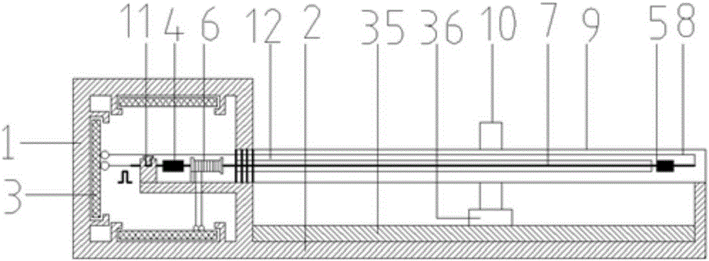
[0045] The displacement meter of this embodiment adopts the above-mentioned connection relationship, and the end part 1 of the displacement meter is a hemispherical cavity structure, on the left circumferential inner wall, top inner wall and lower inner wall of the hemispherical cavity structure, corresponding to the fixed hardware circuit system 3 There are three circuit boards, that is, the power amplification and signal processing module circuit board is fixed on the left peripheral inner wall, the power supply module circuit board is fixed on the top inner wall, and the control module circuit board is fixed on the lower inner wall. A front damping device 4, a detection device 6 and a fixing device 11 are arranged in the cavity of the hemispherical cavity structure; the right bottom of the displacement meter end 1 is connected with the displacement meter base 2; There is a threaded hole for fixedly connecting the measuring rod 9. In this embodiment, the waveguide wire 7 is ...


PUM


Abstract

The invention relates to a magnetostriction micro displacement meter, which is characterized in that the displacement meter comprises a displacement meter end part, a displacement meter base, a measuring rod, a waveguide wire, a linear guide rail and a movable terminal, the displacement meter end part is of a cavity structure, the inner wall of the cavity structure is provided with a hardware circuit system, and a cavity body of the cavity structure is internally provided with a front damping device, a detection device and a fixing device; the bottom part at the right side of the displacement meter end part is connected with the displacement meter base; the center at the right side of the displacement meter end part is provided with a threaded hole, and the left end of the measuring rod is in threaded connection with the threaded hole of the displacement meter end part; the movable terminal is arranged on the measuring rod in a sleeved mode, the linear guide rail is fixed on the displacement meter base along the length direction, the linear guide rail is provided with a sliding block, the upper end of the sliding block is connected with the lower end of the movable terminal, and the sliding block is connected with an external mechanical device; and magnets in the movable terminal adopt a halbach magnet array.

Description

technical field [0001] The invention relates to the technical field of micro-displacement sensors, in particular to a magnetostrictive micro-displacement meter. Background technique [0002] With the development of modern information industry technology, the application range of displacement sensors is becoming wider and wider. Industrial control not only has more requirements for the measurement of large displacements, but also increases the measurement of micro displacements. In terms of micro-displacement measurement, there are many kinds of displacement sensors realized by different principles, such as capacitive, inductive, radar, ultrasonic, Doppler laser and so on. The principles on which it is based mainly include magnetic effect, capacitive effect, photoelectric effect, electromagnetic radiation effect, and mechanical effect. Although these micro-displacement sensors have been widely used in industry, they have quite a lot of shortcomings. Among them, the capaciti...

Claims


Application Information

Patent Timeline
IPC IPC(8): G01B7/02
Inventor 王博文李恒王鹏
Owner HEBEI UNIV OF TECH
Why Eureka
Try Eureka