A high-pressure grouting lifting deformation monitoring device and its installation method

A lifting deformation, high pressure grouting technology, applied in the direction of mechanical solid deformation measurement, etc., can solve the problems affecting the observation accuracy of the lifting deformation observation device, and achieve the effect of ensuring reliability and deformation observation accuracy, and preventing the consolidation of grouting

Active Publication Date: 2018-07-13
POWERCHINA ZHONGNAN ENG
View PDF5 Cites 0 Cited by
  • Summary
  • Abstract
  • Description
  • Claims
  • Application Information

AI Technical Summary

Problems solved by technology

[0003] Aiming at the problem that the existing grouting and lifting deformation observation device is prone to high-pressure grouting and solidification between the protection pipe and the reference pipe, which affects the observation accuracy of the lifting and deformation observation device, a high-pressure grouting and lifting deformation monitoring device and its installation method are proposed. The monitoring device has a multiple sealing structure with elastic rubber plugs between the protection tube and the reference tube, and sealing elements between the sliding outer sleeve and the sliding inner shaft, which can effectively prevent the occurrence of crosstalk between the protection tube and the reference tube during the high-pressure grouting process. To solve the problem of slurry consolidation, to ensure the sealing between the protection tube and the reference tube of the lifting deformation observation device and the free sliding performance of deformation displacement, so as to ensure the observation accuracy of the lifting deformation observation device

Method used


Image

  • A high-pressure grouting lifting deformation monitoring device and its installation method

Examples


Embodiment Construction

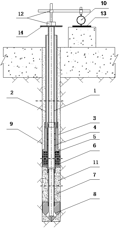
[0034] A high-pressure grouting lifting deformation monitoring device, such as figure 1 As shown, it includes a mounting hole 9, a reference pipe 1, a protection pipe 2, and a ground lift observation dial indicator 10. The installation hole 9 is a specially drilled hole for embedding the reference pipe 1 and the protection pipe 2; the lower end of the reference pipe 1 is connected to the sliding inner shaft 5, the inner anchor pipe 7, and the inner anchor head 8 in sequence; the reference pipe 1 There is a protective tube 2 outside to prevent grouting and grouting; the lower end of the protective tube 2 is connected to the sliding jacket 3; the lower part of the sliding jacket 3 is embedded with an elastic rubber plug 6; the elastic rubber plug 6 is set on the reference pipe 1. The lower sliding inner shaft 5 is embedded and pressed in the shaft shoulder disc; an elastic rubber plug 6 and an O-ring 4 between the sliding outer sleeve and the sliding inner shaft 5 are provided w...


PUM


Abstract

The invention discloses a high-pressure grouting lifting deformation monitoring device and an installation method thereof. The monitoring device includes a reference tube and a protection tube; the inner anchor tube at the bottom of the reference tube and the upper part of the inner anchor head are provided with a sliding inner shaft, and the bottom end of the protection tube is connected with a sliding sleeve, and the sliding sleeve is sleeved on the sliding inner shaft There is a sealing element on and between them; an elastic rubber plug is embedded and pressed between the sliding inner shaft at the lower part of the reference tube and the sliding outer sleeve at the lower part of the protection tube; the top of the reference tube is equipped with a ground lifting observation dial gauge; The reference pipe, the sliding inner shaft, the inner anchor pipe and the inner anchor head all have hollow channels, and each hollow channel is connected in series to form a grouting channel. The invention effectively prevents the grouting and solidification problem between the protection pipe and the reference pipe in the process of high-pressure grouting, and ensures the sealing between the protection pipe and the reference pipe of the lifting deformation observation device and the free sliding performance of deformation displacement, thereby ensuring the lifting and deformation observation device. The observation accuracy of the dynamic deformation observation device.

Description

technical field [0001] The invention relates to a high-pressure grouting lifting deformation monitoring device and an installation method thereof, belonging to the field of foundation treatment consolidation and anti-seepage grouting engineering, and is mainly used for real-time grouting lifting deformation during foundation treatment consolidation and anti-seepage grouting Monitoring to avoid large grouting deformation due to excessive grouting strength, resulting in damage to the superstructure. Background technique [0002] When performing foundation reinforcement and anti-seepage grouting, the grout poured into the pores or cracks of the formation may cause grouting deformation and damage as the amount of grouting and grouting pressure increase. Clay, kelp, butter, gypsum or a single rubber pad is often used for sealing and isolation between the protection pipe and the reference pipe of the existing grouting lifting deformation observation device, which is prone to high-...

Claims


Application Information

Patent Timeline
Patent Type & Authority Patents(China)
IPC IPC(8): G01B5/30
Inventor 陈安重黄灿新舒王强樊凯卢贤伟周运东
Owner POWERCHINA ZHONGNAN ENG
Why Eureka
Try Eureka