Automatic constant-flow connector

An automatic, tapered head technology for pipes/couplings/fittings, connections with fluid shut-offs, engine components, etc., capable of solving problems such as water flow differences

Inactive Publication Date: 2015-12-23
ZHONGSHAN YAXI ENVIRONMENTAL PROTECTION TECH
View PDF6 Cites 2 Cited by
  • Summary
  • Abstract
  • Description
  • Claims
  • Application Information

AI Technical Summary

Problems solved by technology

Due to the difference in water pressure between different floors, even if the water outlet is opened at the same time, the water output is different

Method used


Image

  • Automatic constant-flow connector
  • Automatic constant-flow connector
  • Automatic constant-flow connector

Examples


Embodiment Construction

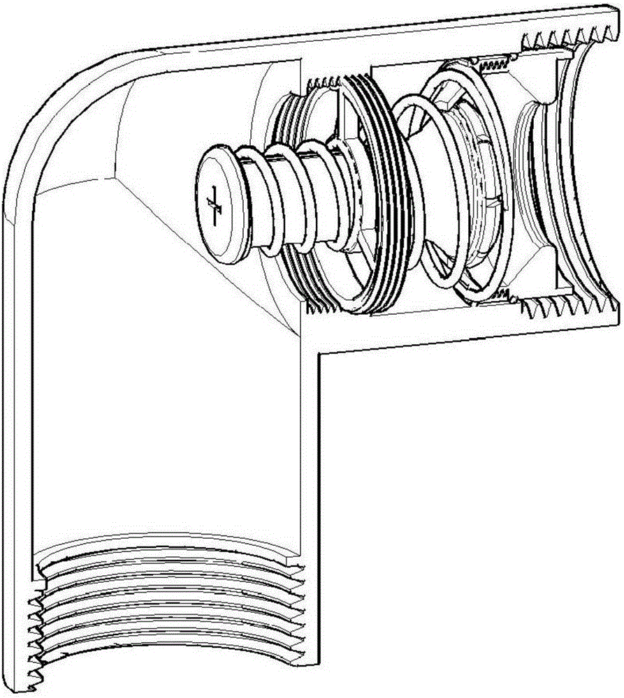
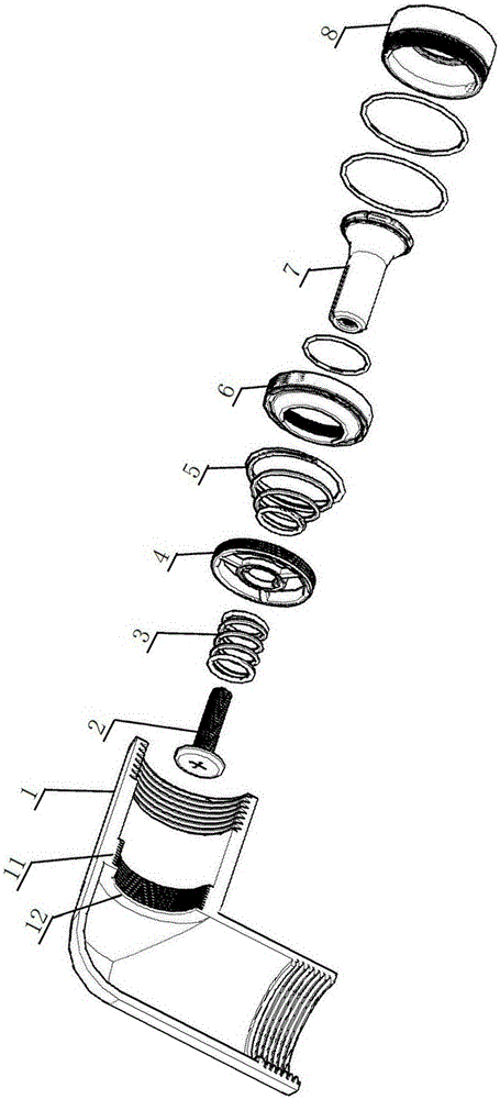
[0021] Such as Figure 1 to Figure 7 As shown, an automatic constant current joint is mainly composed of a joint 1, an adjustment screw 2, an adjustment spring 3, a bracket 4, a tower spring 5, a fixed cover 6, a valve core 7 and a fixed seat 8.

[0022] The inner wall of the joint 1 is provided with a ring of flanges 11 protruding inwards, and the flanges are provided with internal threads matching the external threads of the outer wall of the bracket. The lugs are used to mate with the brackets, which are threaded onto the lugs inside the joint.

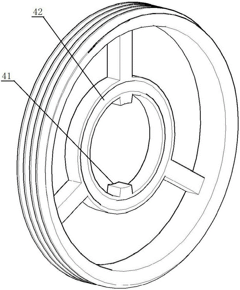
[0023] The bracket 4 is composed of a coaxial outer ring and an inner ring connected by a support arm, the inner wall of the inner ring is provided with a limit protrusion 41 protruding inward, and the valve stem of the valve core 7 is provided with a limit protrusion on the inner ring of the bracket. A corresponding limit groove 71 is formed, and a screw hole 72 coaxial with the valve stem is also provided on the valve stem. By ...


PUM


Abstract

An automatic constant-flow connector is mainly composed of a connector body (1), an adjusting screw (2), an adjusting spring (3), a support (4), a tower-shaped spring (5), a fixed cover (6), a valve element (7) and a fixed seat (8). The automatic constant-flow connector is arranged in an existing pipe network system, and can be inserted in a tool hole in the valve element through a common tool to rotate, and therefore other parts except for the connector body are taken out of the connector body, the compression degree of the adjusting screw on the spring is changed by changing the position of the adjusting screw on a valve rod of the valve element, prestress of the spring is changed, the force needed by pushing a conical head of the valve element into an inner hole of a boss is changed, and the flow per unit time is adjusted from the water outlet end.

Description

technical field [0001] The invention relates to a joint used for regulating fluid flow in a pipe network system, in particular to a joint capable of regulating flow from a water outlet, which belongs to the technology for flow control in the pipe network system. Background technique [0002] In the case of tap water pipe network, oil pipe network and gas pipe network, if there are multiple water outlets, even if the apertures of the water outlets are the same, the fluid pressure at different positions is different, resulting in the amount of fluid flowing out of the water outlets at different positions per unit time. are not the same, or even quite different. [0003] For example, in the connection between tap water pipes, in addition to the extensive use of joints, right-angle elbows are usually used at the corners to realize the diversion of water flow. Due to the difference in water pressure between different floors, even if the water outlet is opened at the same time, t...

Claims


Application Information

Patent Timeline
Patent Type & Authority Applications(China)
IPC IPC(8): F16L29/02F16K17/30
CPCF16L29/02F16K17/30
Inventor 刘毓珍
Owner ZHONGSHAN YAXI ENVIRONMENTAL PROTECTION TECH
Why Eureka
Try Eureka