
A super large reservoir venting valve structure

A venting valve, super-large technology, applied in sliding valves, valve details, valve devices, etc., can solve the problems of unreasonable design of the shroud, venting of large and medium-sized reservoirs, and short service life of the venting valve, etc., to protect facilities and environmental safety, simple structure, and the effect of improving construction progress

Active Publication Date: 2018-08-07
HUBEI PROVINCIAL WATER RESOURCES & HYDROPOWER PLANNING SURVEY & DESIGN INST
View PDF8 Cites 0 Cited by
  • Summary
  • Abstract
  • Description
  • Claims
  • Application Information

AI Technical Summary

Problems solved by technology

[0007] The purpose of the present invention is to solve the problem that the design of the diversion cover of the vent valve in the above background technology is unreasonable, and it cannot be applied to the venting of large and medium-sized reservoirs and the problem that the service life of the vent valve is not long. The structure of large-diameter, medium-pressure-resistant super-large reservoir vent valve

Method used


Image

  • A super large reservoir venting valve structure
  • A super large reservoir venting valve structure
  • A super large reservoir venting valve structure

Examples


Embodiment Construction

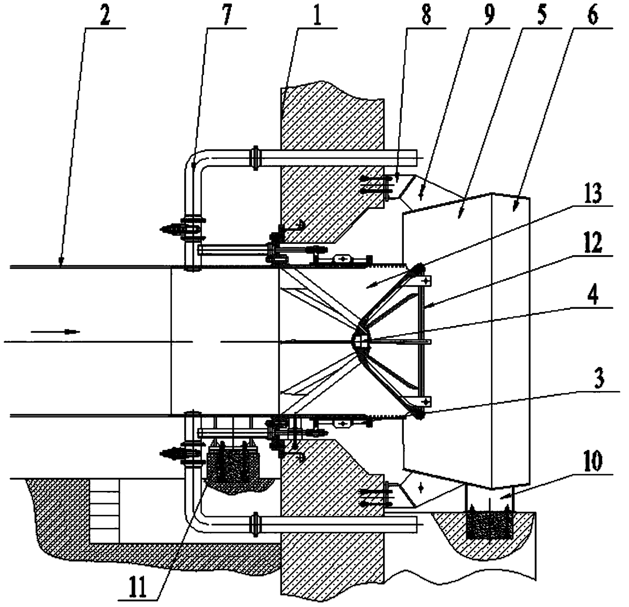
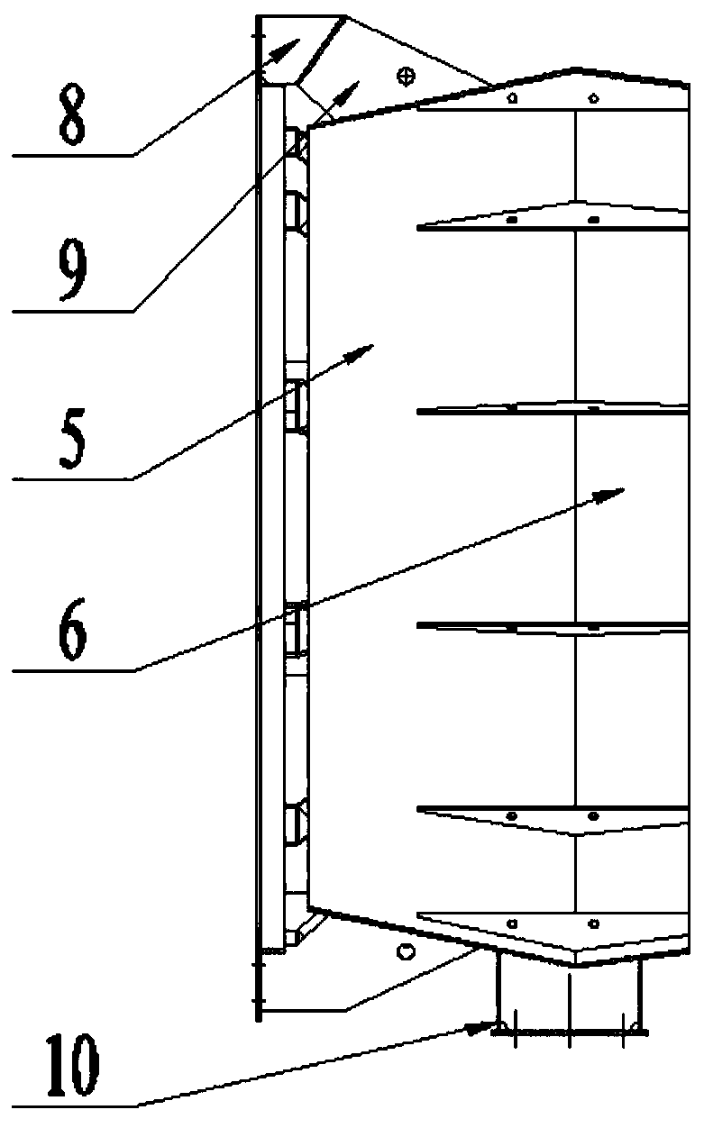
[0026] The present invention will be further described in detail below in conjunction with the accompanying drawings and specific embodiments.

[0027] Such as Figure 1~3 The vent valve used in this embodiment is a cone valve, which includes a valve body 2 fixed on the reinforced concrete foundation 1 of the reservoir. The outer side of the outlet end of the valve body 2 is provided with a sleeve that can slide along the direction of water flow and is coaxial with it. Tube 3, the inner side of the outlet end of valve body 2 is provided with a diversion cone 4 coaxial with the valve body 2, the diversion cone 4 is fixed on the valve body 2, and the tip of the diversion cone 4 faces the water outlet of the valve body 2 At the end, there is a water outlet gap between the diversion cone 4 and the water outlet end of the valve body 2, and the water outlet gap between the diversion cone 4 and the valve body 2 forms a water outlet channel. The sleeve 3 can slide forward to the fart...


PUM


Abstract

The invention relates to the field of reservoir emptying valves of hydraulic power and hydroelectric engineering, in particular to an ultra-large type reservoir emptying valve structure. The ultra-large type reservoir emptying valve structure comprises a valve body. The end of a water outlet of the valve body is sleeved with a sleeve capable of sliding in the water flow direction and coaxial with the valve body, and a flow guiding cone coaxial with the valve body is arranged on the inner side of the end of the water outlet of the valve body. The flow guiding cone is fixed to the valve body, and a gap is reserved between the flow guiding cone and the valve body. The flow guiding cone is in sealing connection with the end of the sleeve sliding to the foremost end, and an opening type flow guiding cover is further included. The flow guiding cover is of an annular structure with the diameter larger than the diameter of the flow guiding cone. The flow guiding cover is arranged outside the flow guiding cone and is coaxial with the flow guiding cone. The ultra-large type reservoir emptying valve structure is simple and convenient to install, has the beneficial effects of being large in diameter and flow, resistant to medium pressure and the like, and can be applied to various large-medium reservoirs. Rapid emptying of a reservoir is facilitated, the construction cost of the reservoir emptying structure is reduced to a great extent, the construction progress of the whole reservoir can be accelerated easily, and extremely high popularization value is achieved.

Description

technical field [0001] The invention relates to the field of reservoir venting valves of hydraulic and hydropower projects, in particular to a super-large reservoir venting valve structure. Background technique [0002] Reservoirs of water conservancy and hydropower projects usually need to be equipped with a venting structure. The venting valve is a common technical means. The venting valve can be used to quickly and safely empty the reservoir. Compared with other venting structures, the venting valve has many advantages. The use of vent valves can save a lot of money compared with the construction of deep-hole gate reservoir venting facilities, and can also replace the mode of using explosion-controlled bolt plugs to open the gates to vent the reservoir, which greatly improves the safety performance of reservoir venting, and can also greatly shorten the reservoir. Water storage period. [0003] The vent valve in the prior art usually uses a shroud to further enhance the o...

Claims


Application Information

Patent Timeline
Patent Type & Authority Patents(China)
IPC IPC(8): F16K3/26F16K3/30F16K47/02B05B1/06
CPCB05B1/06F16K3/265F16K3/30F16K47/023
Inventor 胡新益刘学知罗华牛彬王桥民郭铁桥张北宁陈磊吴红光马雪峰王国勤刘九
Owner HUBEI PROVINCIAL WATER RESOURCES & HYDROPOWER PLANNING SURVEY & DESIGN INST
Learn More