
Mould used on reconstituted bamboo lumber mould pressing production line

A production line and material mold technology, used in household appliances, other household appliances, wood processing appliances, etc., can solve the problems of high labor intensity, weight increase, low work efficiency, etc., to reduce labor intensity, simple operation, and improve work efficiency. Effect

Active Publication Date: 2015-12-23
QINGDAO GUOSEN MACHINERY
View PDF12 Cites 1 Cited by
  • Summary
  • Abstract
  • Description
  • Claims
  • Application Information

AI Technical Summary

Problems solved by technology

However, in the process of square material pressing, if longer recombined bamboo and wood square materials are required, due to the limitation of steel plate rolling capacity, it cannot be manufactured into a mold with the same length as the square material, and the production demand cannot be met; According to the production requirements, square materials with various lengths can be pressed. If the production requirements are matched, it is necessary to be equipped with molds of various lengths, which greatly increases the cost of the molds.
In addition, when the mold is longer, its weight will also increase accordingly, and it requires the cooperation of multiple people to move it to the production line, which is labor-intensive and low-efficiency

Method used


Image

  • Mould used on reconstituted bamboo lumber mould pressing production line
  • Mould used on reconstituted bamboo lumber mould pressing production line
  • Mould used on reconstituted bamboo lumber mould pressing production line

Examples


Embodiment 1

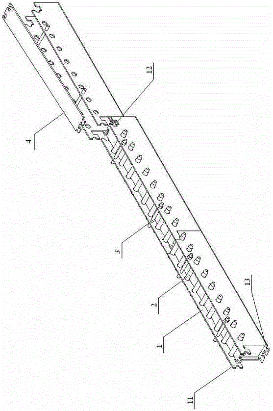
[0038] The U-shaped base groove structure of this embodiment is as follows: Figure 4 shown.

[0039] The structure of the side plate bump head 111 and the side plate bump connection portion 112 is a square structure, the top edge of the side plate bump head 111, the top edge of the side plate bump connection portion 112 and the top edge of the side plate are A straight line, the bottom edge of the side plate bump head 111 is located below the bottom edge of the side plate bump connection portion 112 , that is, the height of the side plate bump head 111 is greater than the height of the side plate bump connection portion 112 .

[0040] The front edge of the side plate bump head is provided with a pin half-hole 151 for installing the pin, and the front edge of the side plate groove 12 is also provided with a pin that cooperates with the side plate bump head pin half hole 151 to form an integral pin hole. Pillar and a half hole; the front single-mode upper side plate groove 12 ...

Embodiment 2

[0047] The difference between this embodiment and Embodiment 1 is that the cross-sectional structure of the bottom plate bump hook 131 is circular, such as Figure 7 shown.

Embodiment 3

[0049] The difference between this embodiment and Embodiment 1 is that the cross-sectional structure of the hook head 131 of the bottom plate bump is trapezoidal, the width of the front end of the hook head 131 of the bottom plate bump is greater than the width of the rear end, and the width of the rear end of the hook head 131 of the bottom plate bump is the same as that of the bottom plate convex hook head 131. Block connection blocks 132 are of equal width, such as Figure 10 with Figure 11 shown.

[0050] In this embodiment, the contact surface between the support block 141 in the groove of the bottom plate and the hook head 131 of the bottom plate bump is a stepped surface with a high front end and a low rear end, as shown in Figure 8 , Figure 10 with Figure 11 shown.

[0051] The three single molds described in this embodiment are used to assemble the mold, and the mold structure after splicing is as follows Figure 8 with Figure 9 shown.


PUM


Abstract

The invention discloses a mould used on a reconstituted bamboo lumber mould pressing production line. The mould comprises a plurality of simple modules which are spliced together in tandem; each simple module comprises a U-shaped foundation trench; each U-shaped foundation trench comprises a left side plate, a bottom plate and a right side plate, which are fixedly connected into a whole; a bottom plate bulge is arranged at the front end part of each bottom plate and located on the same plane as the bottom plate; and a bottom plate groove is formed in the rear end part of each bottom plate and is assembled with the corresponding bottom plate bulge in a matching way. The mould is applied to the reconstituted bamboo lumber mould pressing production line, integrally adopts a tandem splicing structure, and can meet the production requirements of lumbers with different lengths just by adjusting the number of the simple modules.

Description

technical field [0001] The invention relates to the technical field of bamboo and wood processing, in particular to a mold for a molding production line of recombined bamboo and wood squares. Background technique [0002] The recombined bamboo and wood square material molding production line is used to press the broken bamboo material into a square material of any length through a press. Molding production line. The mold used in the production line is a traditional U-shaped mold with a cross-sectional shape. When pressing, put the material into the U-shaped mold. The mold with the material is opened at the bottom of the cavity of the press, and a cover is placed on the material. As the mold cavity formed by the upper and lower crawler chains of the press advances synchronously, the mold continues to advance, and the material and cover plate are gradually compressed into the mold; then the top of the cover plate is pressed by the pins that penetrate the row holes of the mold...

Claims


Application Information

Patent Timeline
Patent Type & Authority Applications(China)
IPC IPC(8): B27N3/08
Inventor 穆国君戴建光
Owner QINGDAO GUOSEN MACHINERY
Learn More