
Medical cleaning rack

A technology for cleaning racks and flushing plates, applied in the field of medical cleaning racks, can solve the problem of high cost, and achieve the effects of improving service life, reducing the use of materials, and improving work stability.

Inactive Publication Date: 2015-12-23
THE AFFILIATED HOSPITAL OF QINGDAO UNIV
View PDF7 Cites 2 Cited by
  • Summary
  • Abstract
  • Description
  • Claims
  • Application Information

AI Technical Summary

Problems solved by technology

[0005] Aiming at the above-mentioned deficiencies in the prior art, the present invention proposes a medical cleaning rack, which solves the problem of high cost of producing different types of existing medical cleaning racks

Method used


Image

  • Medical cleaning rack
  • Medical cleaning rack
  • Medical cleaning rack

Examples


Embodiment 1

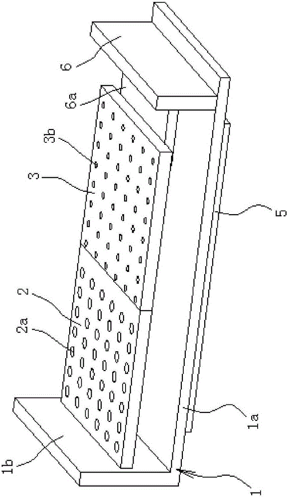
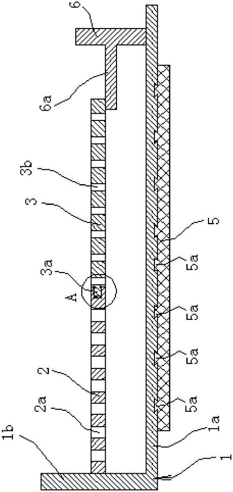
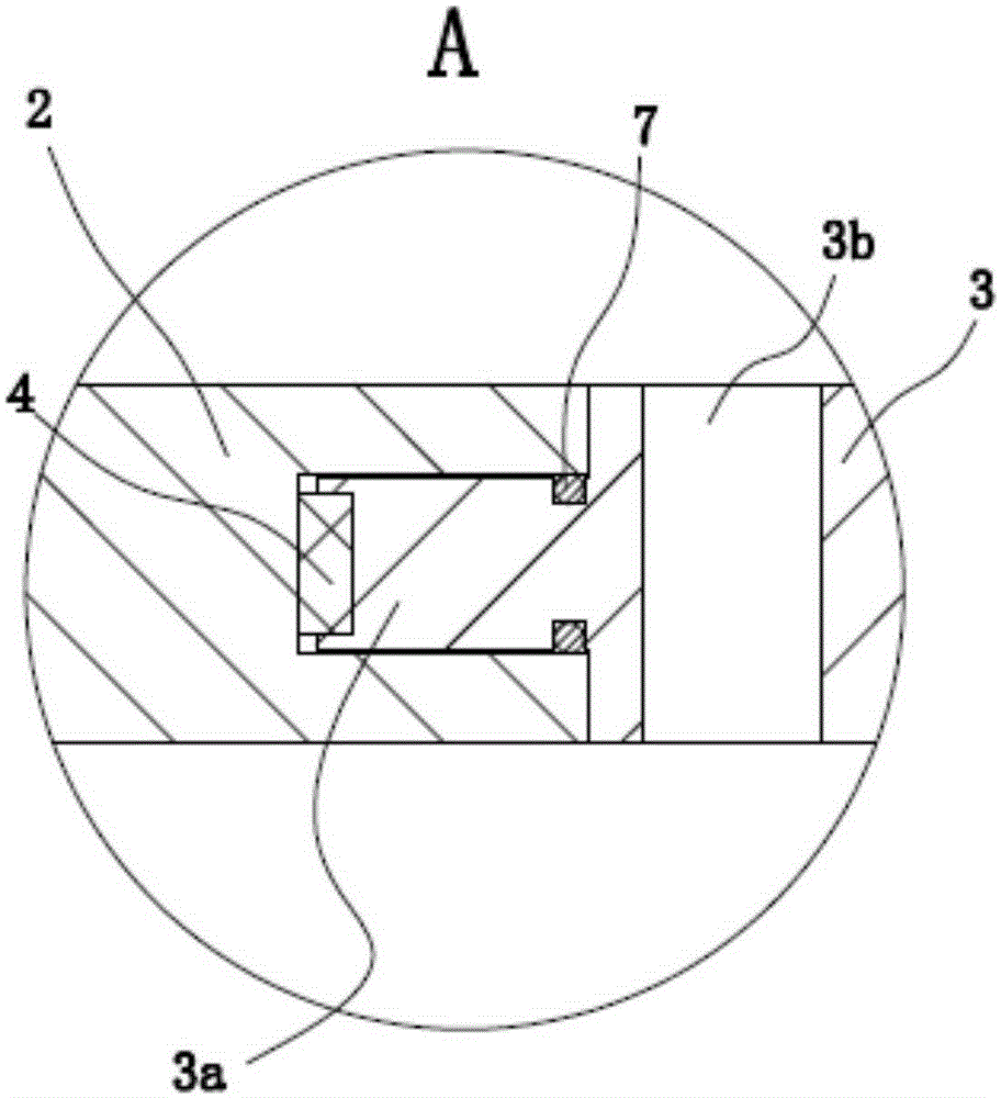
[0036] Such as Figure 1 to Figure 3 Shown, this medical cleaning stand is made up of support 1, flushing plate one 2, flushing plate two 3, magnet 4, rubber pad 5, connecting plate 6 etc. Wherein, the first flushing plate 2 and the second flushing plate 3 are made of magnetically permeable materials, and the magnetically permeable materials can be steel, nickel-iron alloys, and the like. Preferably, both the first flushing plate 2 and the second flushing plate 3 are made of steel.

[0037] The support 1 is L-shaped, and the support 1 includes a horizontal support part 1a and a vertical fixation part 1b, and both the support part 1a and the fixation part 1b are in the shape of a long plate. A rubber pad 5 is attached to the lower side of the support portion 1a, and the rubber pad 5 is fixed to the support portion 1a through a concave-convex connection structure, so that the support portion 1a contacts the ground (or other support portion 1a pieces) through the rubber pad 5 ,...

Embodiment 2

[0044] The structure and principle of this second embodiment are basically the same as that of the first embodiment, except that the sealing member 7 is a ring-shaped rubber layer uniformly coated on the side wall of the connecting part 3a, and the outer wall of the rubber layer is in contact with the The inner walls of the connecting holes are offset.

Embodiment 3

[0046] The structure and principle of this third embodiment are basically the same as that of the first embodiment, except that the concave-convex connection structure includes a limit hole on the lower side of the support part 1a and a protruding hole on the upper side of the rubber pad 5 that is consistent with Connecting posts that match the limit holes. There are at least two limiting holes and they are evenly distributed along the circumferential direction. The limiting holes are tapered and the diameter of the limiting holes gradually decreases downward. The number of connecting columns is the same as that of the limiting holes and the positions correspond to each other, and the connecting columns are embedded in the limiting holes.


PUM


Abstract

The invention provides a medical cleaning rack, and belongs to the technical field of medical instruments. The problem that cost is higher when existing medical cleaning racks of different types are produced is solved. The medical cleaning rack comprises an L-shaped support. The support comprises a horizontal supporting part and a vertical fixed part. A first washing plate and a second washing plate are arranged in the support and are right opposite. One end of the first washing plate and the fixed part are fixed. A plurality of connecting parts protruding in a columnar shape are arranged on the end face of the second washing plate. Connecting holes with the number equal to that of the connecting parts are formed in the other end face of the first washing plate, and the connecting holes correspond to the connecting parts one to one in position. The connecting parts are inserted in the connecting holes. Magnets abutting against the inner walls of the connecting holes are arranged in the connecting holes and, and magnets and the connecting parts are fixed. Sealing pieces capable of sealing openings of the connecting holes are arranged on the connecting parts. First through holes and second through holes are formed in the first washing plate and the second washing plate respectively. The medical cleaning rack has the beneficial effect that cost is low when the cleaning racks of different types are produced.

Description

technical field [0001] The invention belongs to the technical field of medical instruments, and relates to a medical washing rack. Background technique [0002] With the implementation of the centralized supply mode of the disinfection supply center, there are more and more types of cleaning items, and some items are complex in structure, and the cleaning quality is difficult to guarantee. Lumen items such as regenerated puncture needles, endotracheal cannula, etc. must go through multiple procedures such as flushing, ultrasonic cleaning, punching and drilling, and the recovered puncture needles are placed in separate stainless steel trays. During the whole cleaning process, it needs to be taken out and put down several times, and the puncture needle is placed in the separated stainless steel plate, which may easily cause collision and confusion, damage the needle tip, and also bring difficulties to the matching. The whole process is time-consuming. [0003] For the above p...

Claims


Application Information

Patent Timeline
Patent Type & Authority Applications(China)
IPC IPC(8): B08B3/02B08B13/00
CPCB08B3/02B08B13/00
Inventor 李斌
Owner THE AFFILIATED HOSPITAL OF QINGDAO UNIV
Learn More