Dry ice particle treatment device and dry ice particle treatment method

A processor and particle technology, applied in the direction of grain processing, etc., can solve the problems of large destructive force, large particle diameter, and inability to clean instruments or equipment, and achieve the effect of reducing labor costs, reducing labor intensity, and meeting the requirements of mechanical automation operations

Inactive Publication Date: 2015-12-23
HARBIN DERUISIWO SCI & TECH CO LTD
View PDF4 Cites 2 Cited by
  • Summary
  • Abstract
  • Description
  • Claims
  • Application Information

AI Technical Summary

Problems solved by technology

[0007] In order to solve the problem that the particle diameter of the existing dry ice particles is large, the destructive force is large, and the instruments or equipment with high precision requirements cannot be cleaned, resulting in a blank particle cleaning in the domestic dry ice cleaning industry, a dry ice cleaning method is proposed. Particle processor and method of processing the same

Method used


Image

  • Dry ice particle treatment device and dry ice particle treatment method
  • Dry ice particle treatment device and dry ice particle treatment method
  • Dry ice particle treatment device and dry ice particle treatment method

Examples


specific Embodiment approach 1

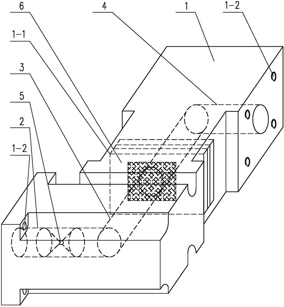
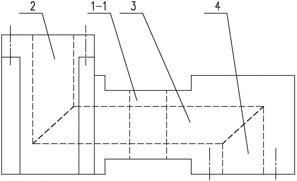
[0025] Specific implementation mode one: combine Figure 1 to Figure 6 Describe this embodiment, a dry ice particle processor described in this embodiment includes an outer casing 1, a first pipeline 2, a second pipeline 3, a third pipeline 4, a throat 5 and a sieve plate 6, the first pipeline 2, the second pipeline The second pipeline 3 and the third pipeline 4 are arranged in the outer casing 1 respectively, one end of the first pipeline 2 is connected with the outlet of the material supply assembly, and the other end of the first pipeline 2 is vertically connected with one end of the second pipeline 3 , the other end of the second pipeline 3 is vertically connected with one end of the third pipeline 4, the other end of the third pipeline 4 is connected with the ice outlet pipe, the throat pipe 5 is arranged in the first pipeline 2, and the throat pipe 5 includes two cones Pipe 5-1, the two conical pipes 5-1 are arranged opposite to each other horizontally, the tips of the t...

specific Embodiment approach 2

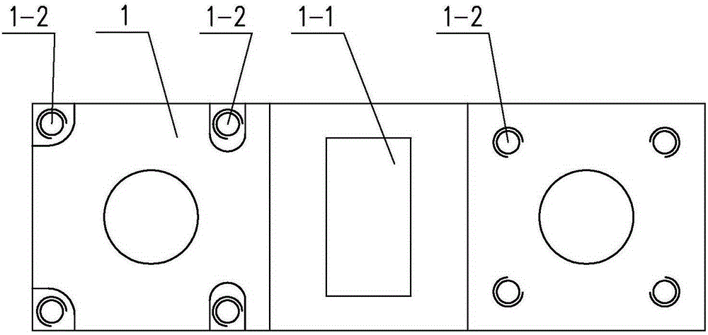
[0028] Specific implementation mode two: combination Figure 1 to Figure 3 To illustrate this embodiment, the outer casing 1 in this embodiment is provided with a slot 1-1, the slot 1-1 is arranged perpendicular to the axial direction of the second pipeline 3, and the sieve plate 6 is inserted into the slot 1-1 . The undisclosed technical features in this embodiment are the same as those in the first embodiment.

[0029] With such a design, when the sieve plate 6 needs to be cleaned, maintained or replaced, it is only necessary to pull the sieve plate 6 out of the slot 1-1 to facilitate its disassembly and installation.

specific Embodiment approach 3

[0030] Specific implementation mode three: combination Figure 1 to Figure 3 , Figure 5 and Figure 6 To illustrate this embodiment, the sieve plate 6 in this embodiment is provided with a screen 6 - 1 , and the edge of the screen 6 - 1 is arranged outside the second pipeline 3 . The undisclosed technical features in this embodiment are the same as those in the first or second specific embodiment.

[0031] This design ensures that all the dry ice particles are impacted and pulverized on the screen 6-1 before passing through.


PUM


Abstract

The invention relates to a treatment device and a treatment method, and discloses a dry ice particle treatment device and a dry ice particle treatment method to solve the problems that the conventional dry ice particles are high in particle diameter and high in destructive power, and can not clean an instrument or an equipment having higher requirement on the accuracy, resulting in a blank of particle cleaning in the dry ice cleaning industry in China. The dry ice particle treatment device comprises an outer housing, a first pipeline, a second pipeline, a third pipeline, a throat pipe and a sieve plate, wherein the first pipeline, the second pipeline and the third pipeline are arranged in the outer housing; one end of the first pipeline is connected with a discharge port of a feeding assembly; the other end of the first pipeline is vertically communicated with one end of the second pipeline; the other end of the second pipeline is vertically communicated with the third pipeline; the throat pipe is arranged in the first pipeline; and the sieve plate is vertically mounted on the second pipeline in an inserting manner. The dry ice particle treatment method comprises the steps of setting a position of the outer housing, conveying materials, carrying out four times of crushing, and outputting the particles. The dry ice particle treatment device and the dry ice particle treatment method are applied to the crushing treatment of the dry ice particles.

Description

technical field [0001] The invention relates to a dry ice particle processor and a processing method for dry ice particles. Background technique [0002] The temperature of dry ice particles is extremely low (-78°C). Such a low temperature makes it have unique thermodynamic properties, which affect the mechanical properties of adhered dirt. Due to the temperature difference between the dry ice particles and the cleaning surface, when the dry ice particles are in contact with the material, thermal shock occurs, the temperature of the material decreases, the brittleness increases, and physical changes occur, so that the dry ice particles can impact and break the dirt layer. [0003] The characteristic of dry ice blasting is that the dry ice particles vaporize at the moment of impact, and the momentum of the dry ice particles disappears at the moment of impact. Rapid heat exchange occurs between the dry ice particles and the cleaning surface to achieve solid CO 2 Rapid sublim...

Claims


Application Information

Patent Timeline
Patent Type & Authority Applications(China)
IPC IPC(8): B02C23/08B02C23/10
Inventor 刘国基夏青
Owner HARBIN DERUISIWO SCI & TECH CO LTD
Why Eureka
Try Eureka