
Pulse Frequency Modulation Circuit Based on Reference Voltage Comparator Oscillator

A pulse frequency modulation and reference voltage technology, applied in the electronic field, can solve the problems of high output ripple and unsatisfactory control method, and achieve the effect of cycle stability and ripple reduction.

Active Publication Date: 2019-03-12
SPREADTRUM COMM (SHANGHAI) CO LTD
View PDF5 Cites 0 Cited by
  • Summary
  • Abstract
  • Description
  • Claims
  • Application Information

AI Technical Summary

Problems solved by technology

In the prior art, when the load is light, the PWM converter can automatically switch to a low power consumption mode to minimize battery current consumption, by intermittently sending out pulse signals to achieve constant frequency by reducing the number of switching times , increase the duty cycle to improve light load and standby efficiency, the waveform of the pulse modulation signal PFM1 in this mode is as follows figure 1 As shown, however, this method will cause higher output ripple, and the control method is not ideal

Method used


Image

  • Pulse Frequency Modulation Circuit Based on Reference Voltage Comparator Oscillator
  • Pulse Frequency Modulation Circuit Based on Reference Voltage Comparator Oscillator
  • Pulse Frequency Modulation Circuit Based on Reference Voltage Comparator Oscillator

Examples


specific Embodiment

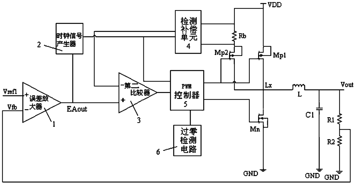
[0090] In a specific embodiment, the feedback network includes a first resistor R1 and a second resistor R2 connected in series, and the feedback voltage signal is drawn from a node where the first resistor R1 and the second resistor R2 are connected.

[0091] As a preferred embodiment of the present invention, the current detection circuit includes:

[0092] A detection resistor Rb, connected in series with the current detection circuit;

[0093] A detection compensation unit 4, connected to both ends of the detection resistor Rb, to detect the current flowing through the detection resistor;

[0094] A detection control switch Mp2 controlled on and off by the pulse modulation signal is connected to the current detection circuit.


PUM


Abstract

A pulse frequency modulation circuit based on a reference voltage comparison oscillator relates to a switch power supply circuit. The circuit comprises a work circuit, a control circuit, a clock signal generator, a first comparator and an adjusting unit. The work circuit is switched between a charge mode and a discharge mode under the effect of pulse modulation signals. The control circuit generates pulse modulation signals according to a first reference voltage, voltage feedback signals and frequency variable clock signals. The control circuit includes an error amplifier for providing error amplification signals. The first comparator compares voltages on the two ends of a second energy storage element with a second reference voltage, and generates transformed high and low levels which serve as clock signals. The adjusting unit receives control of the error amplification signals, and selects one of voltage reference signals different in voltage as a second reference voltage. The output of the error amplification signals directly controls the frequency of the clock signals, so periods are steadily and ripples of output voltages are minimized.

Description

technical field [0001] The invention relates to the field of electronic technology, in particular to a switching power supply circuit. Background technique [0002] Pulse Width Modulation (PWM) and Pulse Frequency Modulation (PFM) are two major categories of DC-DC converter architectures, each type is efficient at heavy and light loads, load regulation, design The performance characteristics are different in terms of complexity, because the load level may change significantly during the entire circuit operation, from 1 to 2 mA during sleep, and up to several hundred mA during normal operation. In the prior art, when the load is light, the PWM converter can automatically switch to a low power consumption mode to minimize battery current consumption, by intermittently sending out pulse signals to achieve constant frequency by reducing the number of switching , increase the duty cycle to improve light load and standby efficiency, the waveform of the pulse modulation signal PFM...

Claims


Application Information

Patent Timeline
Patent Type & Authority Patents(China)
IPC IPC(8): H02M3/156H02M3/157
Inventor 樊茂
Owner SPREADTRUM COMM (SHANGHAI) CO LTD
Learn More