
Low-speed high-torque hybrid magnetic material permanent-magnet fault-tolerant motor

A permanent magnet fault-tolerant, high-torque technology, applied in the field of motors and electrical engineering, can solve the problems of adjacent permanent magnet flux leakage, large amount of rare earth permanent magnet materials, insufficient use of stator space, etc., to reduce cogging torque , increase the volume of the motor, improve the effect of output torque

Active Publication Date: 2015-12-16
JIANGSU UNIV
View PDF4 Cites 9 Cited by
  • Summary
  • Abstract
  • Description
  • Claims
  • Application Information

AI Technical Summary

Problems solved by technology

[0005] The present invention is a low-speed high-torque hybrid motor designed to solve the problems of the existing surface-mounted permanent magnet vernier motors, such as the large amount of rare earth permanent magnet materials, serious magnetic flux leakage between adjacent permanent magnet poles, and insufficient use of stator space. Magnetic material permanent magnet fault-tolerant motor

Method used

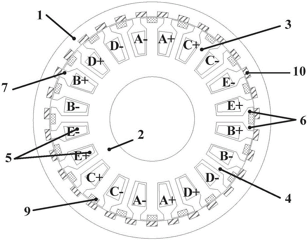
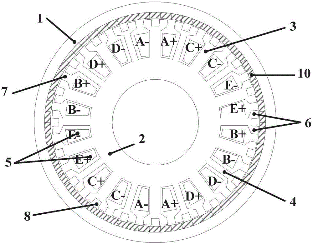
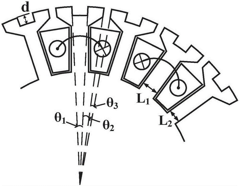

Image

  • Low-speed high-torque hybrid magnetic material permanent-magnet fault-tolerant motor
  • Low-speed high-torque hybrid magnetic material permanent-magnet fault-tolerant motor
  • Low-speed high-torque hybrid magnetic material permanent-magnet fault-tolerant motor

Examples


Embodiment Construction

[0026] The following will clearly and completely describe the technical solutions in the embodiments of the present invention with reference to the drawings in the embodiments of the present invention.

[0027] In describing the present invention, it should be understood that the terms "center", "longitudinal", "transverse", "upper", "lower", "front", "rear", "left", "right", " The orientations or positional relationships indicated by "vertical", "horizontal", "top", "bottom", "inner" and "outer" are based on the orientations or positional relationships shown in the drawings, and are only for the convenience of describing the present invention and Simplified descriptions, rather than indicating or implying that the device or element referred to must have a particular orientation, be constructed and operate in a particular orientation, and thus should not be construed as limiting the invention. In addition, the terms "first" and "second" are used for descriptive purposes only, ...


PUM

PropertyMeasurementUnit
Depthaaaaaaaaaa

Abstract

The invention discloses a low-speed high-torque hybrid magnetic material permanent-magnet fault-tolerant motor. The motor is a type of a rotor permanent magnet and comprises an external rotor and an internal stator, wherein a single-polarity NdFeB permanent-magnet material radially magnetized is embedded into the external rotor, the internal stator comprises armature teeth and the fault-tolerant teeth, the armature teeth and the fault-tolerant adopt different tooth widths to increase the groove area to the greatest extent, small grooves are formed in the teeth to form equivalent-width modulation poles, ferrites radially magnetized are embedded into the small grooves, and the armature teeth are wound with a single-layer concentrated winding. In the hybrid magnetic material permanent-magnet fault-tolerant motor, the limited space of the stator is fully utilized, the ferrite materials are embedded into the small grooves on the stator teeth which are not uniformly distributed at the periphery of the stator, the interpolar magnetic leakage of the permanent magnet on the rotor and the cogging torque of the motor are reduced, the utilization rate of the permanent magnet is improved, and the power density of the motor is enhanced as well as the fabrication cost is reduced.

Description

technical field [0001] The invention relates to the fields of electric engineering and motors, in particular to a low-speed and high-torque hybrid magnetic material permanent magnet fault-tolerant motor. Background technique [0002] In recent years, direct drive technology has developed rapidly. Because of its many advantages such as no transmission gap, no wear and high reliability, it is more and more widely used in high-speed machining centers and industrial master machines. In direct drive technology, the key lies in whether the motor can meet the performance requirements of low speed and high torque. [0003] Under the premise of ensuring the output torque, there are two ways to reduce the speed of the AC motor: increasing the number of poles and reducing the frequency. Too many poles will increase the volume of the asynchronous motor; while the frequency is too low, the induced electromotive force will decrease. In order to maintain the value of the induced electromo...

Claims


Application Information

Patent Timeline
IPC IPC(8): H02K21/22H02K3/28H02K1/27H02K1/16
Inventor 刘国海陈鸣赵文祥吉敬华陈前赵万祥
Owner JIANGSU UNIV
Learn More