
Spatial distinguishing radiant flux detection apparatus

A detection equipment and spatial resolution technology, which is applied in the field of X-ray detection, can solve the problem that diagnostic equipment cannot perform quantitative detection of radiation flow with time and space resolution at the same time, and achieve the effect of broad application prospects

Active Publication Date: 2015-12-16
LASER FUSION RES CENT CHINA ACAD OF ENG PHYSICS
View PDF5 Cites 24 Cited by
  • Summary
  • Abstract
  • Description
  • Claims
  • Application Information

AI Technical Summary

Problems solved by technology

[0004] In order to overcome the deficiency that the diagnostic equipment in the prior art cannot perform quantitative detection of radiation flow with time and space resolution at the same time, the present invention provides a detection device for radiation flow with spatial resolution

Method used


Image

  • Spatial distinguishing radiant flux detection apparatus
  • Spatial distinguishing radiant flux detection apparatus
  • Spatial distinguishing radiant flux detection apparatus

Examples


Embodiment 1

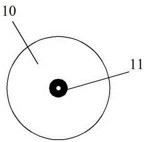
[0030] figure 1 It is a schematic diagram of the optical path structure of the spatially resolved radiation flow detection device of the present invention, figure 2 It is a schematic structural diagram of the pinhole lens assembly in the spatially resolved radiation flow detection device of the present invention, in figure 1 , figure 2 Among them, the spatially resolved radiation flow detection device of the present invention includes a camera 4, a pinhole lens assembly 3, a hole-limited imaging plate 5, a hole-limited plate 6, and a flat-response X-ray detector F-XRD7 arranged in sequence on the optical path. The pinhole lens assembly 3 includes a pinhole plate 11 and an annular lens 10 , and the pinhole plate 11 is nested in the middle of the annular lens 10 . The hole-limiting imaging plate 5 is pasted on the hole-limiting plate 6 . The pinhole center on the pinhole plate 11, the hole-limiting center of the hole-limiting imaging plate 5, the hole-limiting center of the...

Embodiment 2

[0050] The structure of this embodiment is the same as that of Embodiment 1, except that the angle between the line of sight of the camera 4 and the straight line of the optical path is 40°, the diameter of the pinhole of the pinhole plate is 80um, and the diameter of the pinhole plate is 80um. The pinhole plate is a tantalum sheet with a thickness of 20um. The hole diameter of the hole-limiting imaging plate 5 and the hole-limiting plate 6 is 3mm, and the hole-limiting plate 6 is a tantalum sheet with a thickness of 20um.


PUM

PropertyMeasurementUnit
Thicknessaaaaaaaaaa
Thicknessaaaaaaaaaa
Pinhole diameteraaaaaaaaaa

Abstract

The invention provides a spatial distinguishing radiant flux detection apparatus, which comprises a pinhole lens assembly, a camera, an aperture-limiting imaging plate, an aperture-limiting plate and a flat response X-ray detector F-XRD; a black chamber inlet emits visible light; a lens produces image onto the aperture-limiting imaging plate; the X-ray emitted from the black chamber inlet passes through the pinhole after determining the position relation of the aperture and the visible light image in the inlet; only part of the X-ray passes through the aperture-limiting imaging plate and the aperture of the aperture-limiting plate and gets to a sensitive surface of the flat response X-ray detector F-XRD to trigger response; that X-ray energy flow is correspond to a radiant flux of part area inside the inlet; at the same time, the aperture-limiting imaging plate records the position relation between X-ray image and the aperture after passing though the pin hole of the inlet so as to realize spatial distinguishing radiant flux detection. According to the invention, the X-ray radiant flux quantitative detection can be distinguished in time and space without being influenced by extra X-ray generated at the edge of the black chamber inlet of laser; and a wide application prospect is provided.

Description

technical field [0001] The invention belongs to the field of X-ray detection, and in particular relates to a spatial resolution radiation flow detection device. Background technique [0002] Laser-driven black cavities are capable of converting laser energy into near-Planckian soft X-rays, and are often used in indirectly driven inertial confinement fusion ICF. The measured X-rays can be used to deduce the radiation temperature, which is one of the most important parameters of the black cavity radiation source and the basis for exploring the physical process of the interaction between the laser and the black cavity. However, the spatially resolved detection of the X-ray radiation flow in a specific region (non-spot, spot or pellet) inside the black cavity is an unresolved and very important problem in indirectly driven ICF experiments. [0003] However, the existing diagnostic equipment has the following deficiencies: 1. Because the inner diameter of the injection port of t...

Claims


Application Information

Patent Timeline
IPC IPC(8): G01T1/29
Inventor 任宽刘慎业侯立飞杜华冰景龙飞赵阳杨志文韦敏习邓克立姚立杨国洪李三伟江少恩丁永坤
Owner LASER FUSION RES CENT CHINA ACAD OF ENG PHYSICS
Learn More