
Measurement target base and full-aircraft landmark measurement system

A technology for measuring targets and bases, which is applied in the field of measuring target bases and whole-machine measuring landmark systems, and can solve the problem of inability to adjust the coordinates of the center of the target ball through horizontal adjustment, the target ball and the target base are easy to be touched, and affect the staff and workers. Problems such as equipment passing through, to achieve the effect of reducing the cost of measuring equipment, facilitating the promotion and application, and reducing the workload of measurement

Active Publication Date: 2015-12-16
中航通飞华南飞机工业有限公司
View PDF5 Cites 5 Cited by
  • Summary
  • Abstract
  • Description
  • Claims
  • Application Information

AI Technical Summary

Problems solved by technology

For this reason, some laser trackers are combined with target balls (landmark points) for measurement, but these target balls are arranged along the shape of the aircraft, which may easily block the sight of the target ball, resulting in inaccurate or impossible measurement, and extremely poor performance. Stable; and the target bases of these target balls are generally placed directly on the ground of the factory building, and the target balls are then placed on the target base. Every time you measure, you need to reset and set the target base, and move and adjust repeatedly. Greatly increase the labor intensity of the testers, the measurement accuracy is unstable, and the test efficiency is very low, and the target ball and the target seat are also easy to be touched, which not only affects the accuracy of the landmark points, increases the repair work, but also affects the staff on the road Passing through the equipment will inevitably cause contact and stumbling, and it is easy to fall and injure the workers, posing safety hazards
[0003] In addition, the existing target bases simply set the target ball mounting holes on the upper surface, and do not have other functions. Adjustment, measurement accuracy cannot be guaranteed

Method used


Image

  • Measurement target base and full-aircraft landmark measurement system
  • Measurement target base and full-aircraft landmark measurement system
  • Measurement target base and full-aircraft landmark measurement system

Examples


Embodiment Construction

[0025] In order to make the object, technical solution and advantages of the present invention clearer, the present invention will be further described in detail below in conjunction with the accompanying drawings and embodiments. It should be understood that the specific embodiments described here are only used to explain the present invention, not to limit the present invention.

[0026] Such as figure 1 with figure 2 as shown in:

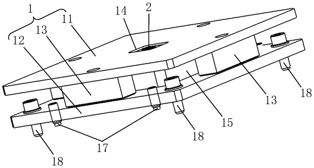
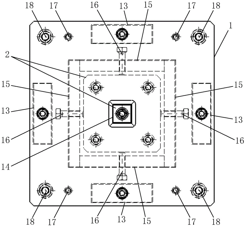
[0027] The embodiment of the present invention provides a measurement target base, including a target base 1 and a positioning block 2, the target base 1 is mainly composed of a protective cover 11 and a fixed base 12, the protective cover 11 and the fixed base 12 Arranged in parallel with each other and connected and fixed together; the positioning block 2 can be moved back and forth, left and right, and adjusted, and is arranged between the protective cover 11 and the fixed base 12, and the upper surface of the protective cover 11 is provide...


PUM


Abstract

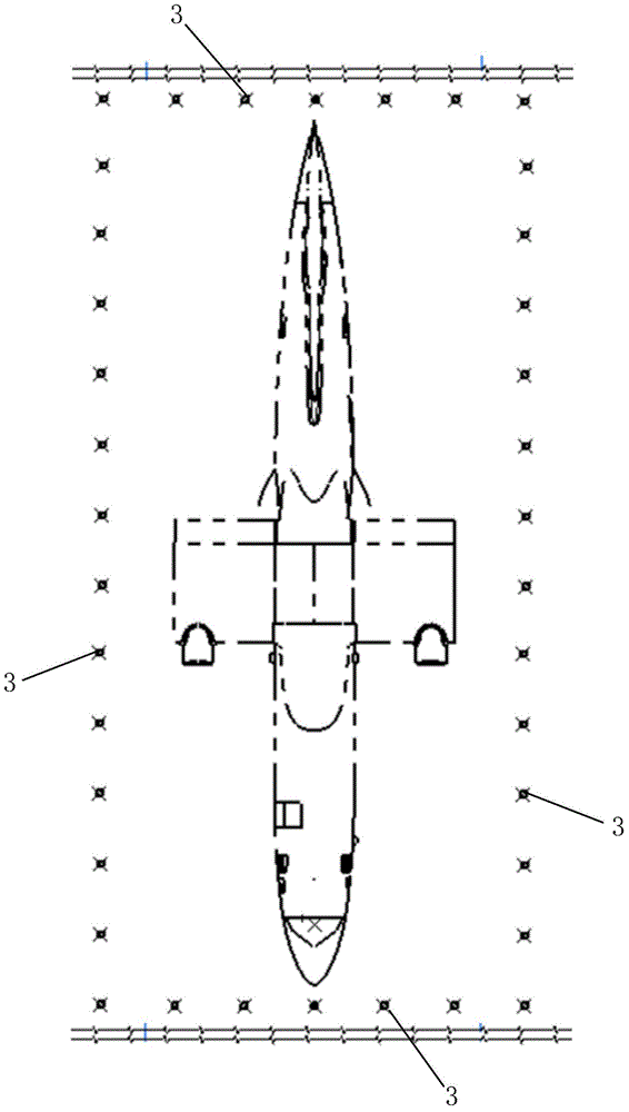
The invention relates to a measurement target base and a full-aircraft landmark measurement system. The measurement target base comprises a target seat and a positioning block, wherein the target seat mainly comprises a protecting cover plate and a fixing base which are mutually parallel and integrally connected and fixed; the positioning block adjustably moves forwards and backwards and rightwards and leftwards and is arranged between the protecting cover plate and the fixing base, a positioning hole is formed in the upper surface of the protecting cover plate, and the positioning block is located right below the positioning hole. Accordingly, the central coordinates of a target ball placed in the positioning hole can be adjusted, the use is flexible and convenient, the operation is simple, and the measurement accuracy of the central coordinates of the target ball on the target seat by a laser tracker is effectively improved; according to the full-aircraft landmark measurement system comprising a plurality of measurement target bases uniformly distributed in a rectangular manner with the symmetric center line of a to-be-measured aircraft as a center, the coverage for landmark measurement is wide, the measurement accuracy and safety performance are high, station transferring is convenient, the measurement target bases are not required to be rearranged, and the economic benefit is huge.

Description

technical field [0001] The invention belongs to the technical field of whole-machine measurement, and in particular relates to a measurement target base and a whole-machine measurement landmark system. Background technique [0002] At present, when the level measurement of the whole aircraft is carried out at home and abroad, the level is generally used to complete it, the measurement accuracy is extremely poor, and the measurement efficiency is extremely low. For this reason, some laser trackers are now used in combination with target balls (landmark points) for measurement, but these target balls are arranged along the shape of the aircraft, which may easily block the sight of the target ball, resulting in inaccurate or impossible measurement, and extremely poor performance. Stable; and the target bases of these target balls are generally placed directly on the ground of the factory building, and the target balls are then placed on the target base. Every time you measure, ...

Claims


Application Information

Patent Timeline
Patent Type & Authority Applications(China)
IPC IPC(8): G01C15/00
CPCG01C15/002
Inventor 付景丽肖鼎王彬冯万喜
Owner 中航通飞华南飞机工业有限公司
Learn More