Method for measuring deformation of effect target with laser
A technology of laser measurement and laser distance measurement, which is applied to volume measurement instruments/methods, measurement devices, and measurement capacity, etc. It can solve the problems of difficult control of measurement stability, slow filling and metering of fillers, and difficulty in obtaining data on site. Achieve the effect of fast measurement speed, less human error, and convenient follow-up research
- Summary
- Abstract
- Description
- Claims
- Application Information
AI Technical Summary
Problems solved by technology
Method used
Image
Examples
Embodiment 1
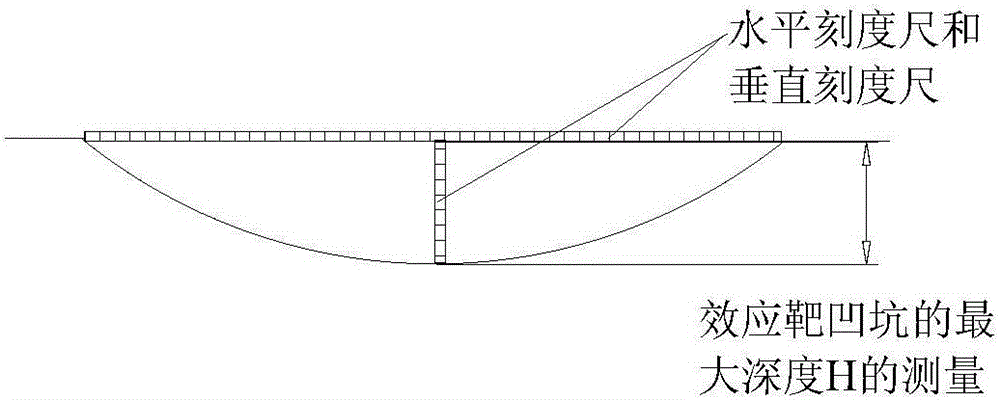
[0053] In this embodiment, the effect target is a circular thin aluminum plate of Φ300mm×2mm. The maximum deformation depth H and the pit volume V of the effect target after the shock wave with a peak value of 0.37MPa are measured as 24.5mm and 307ml respectively by traditional methods. Now use the method of the present invention to measure the maximum deformation depth H and pit volume V of the effect target, and the specific steps are as follows:
[0054] (a) Calibrate the relative position of the laser light source and the effect target
[0055] like Figure 4 As shown, the effect target is placed horizontally, so that the effect target plane is in a horizontal state, and the maximum depth point of the effect target pit is marked, that is, the geometric center of the pit, which is recorded as o. Adjust the position of the laser distance measuring device so that the laser distance measuring device is located directly above the deformation pit of the effect target and is per...
Embodiment 2
[0067] In this embodiment, the effect target is a circular thin aluminum plate of Φ150 mm × 2 mm. The maximum deformation depth H and the pit volume V of the effect target after the shock wave with a reflection pressure peak value of 9 MPa (internal explosion) are measured by traditional methods as 20.6mm and 105ml. Now use the method of the present invention to measure the maximum deformation depth H and pit volume V of the effect target, and the specific steps are as follows:
[0068] (a) Calibrate the relative position of the laser light source and the effect target
[0069] like Figure 4 As shown, the effect target is placed horizontally, so that the effect target plane is in a horizontal state, and the maximum depth point of the effect target pit is marked, that is, the geometric center of the pit, which is recorded as o. Adjust the position of the laser distance measuring device so that the laser distance measuring device is located directly above the deformation pit ...
Embodiment 3
[0081] In this embodiment, the effect target is a round thin aluminum plate of Φ800mm×2mm. The maximum deformation depth H and pit volume V of the effect target after the shock wave with a peak value of 0.13MPa are measured by traditional methods to be 14.5mm and 583ml respectively. Now use the method of the present invention to measure the maximum deformation depth H and pit volume V of the effect target, and the specific steps are as follows:
[0082] (a) Calibrate the relative position of the laser light source and the effect target
[0083] like Figure 4 As shown, the effect target is placed horizontally, so that the effect target plane is in a horizontal state, and the maximum depth point of the effect target pit is marked, that is, the geometric center of the pit, which is recorded as o. Adjust the position of the laser distance measuring device so that the laser distance measuring device is located directly above the deformation pit of the effect target and is perpend...
PUM
 Abstract
Description
Claims
Application Information
 - R&D
- Intellectual Property
- Life Sciences
- Materials
- Tech Scout
- Unparalleled Data Quality
- Higher Quality Content
- 60% Fewer Hallucinations
Browse by: Latest US Patents, China's latest patents, Technical Efficacy Thesaurus, Application Domain, Technology Topic, Popular Technical Reports.
© 2025 PatSnap. All rights reserved.Legal|Privacy policy|Modern Slavery Act Transparency Statement|Sitemap|About US| Contact US: help@patsnap.com


