Rotating shaft locking device of transmission mechanism

A transmission mechanism and locking device technology, applied in the direction of electromechanical devices, rotating shafts, electric components, etc., can solve the problems of high power of the drive motor, low efficiency of the transmission chain, interference with the turntable, etc., and achieve high locking precision, lock High reliability and improved stability

Active Publication Date: 2015-12-16
NO 771 INST OF NO 9 RES INST CHINA AEROSPACE SCI & TECH
View PDF5 Cites 6 Cited by
  • Summary
  • Abstract
  • Description
  • Claims
  • Application Information

AI Technical Summary

Problems solved by technology

[0002] The shaft locking of existing transmission mechanisms such as turntables mainly relies on the self-locking function of its transmission components, such as the self-locking property of worm gears or electromagnetic clutches. Using worm gears as self-locking mechanisms for rotating shafts requires self-locking of worm gears and worms. The lock function results in the low efficiency of the transmission chain and the disadvantage of high motor power of the drive motor. Using an electromagnetic clutch as a locking mechanism has the problems of large volume and large magnetic interference of the electromagnet to the work of the precision parts of the turntable.

Method used


Image

  • Rotating shaft locking device of transmission mechanism
  • Rotating shaft locking device of transmission mechanism
  • Rotating shaft locking device of transmission mechanism

Examples


Embodiment Construction

[0028] The present invention will be further described in detail below in conjunction with specific embodiments, which are explanations of the present invention rather than limitations.

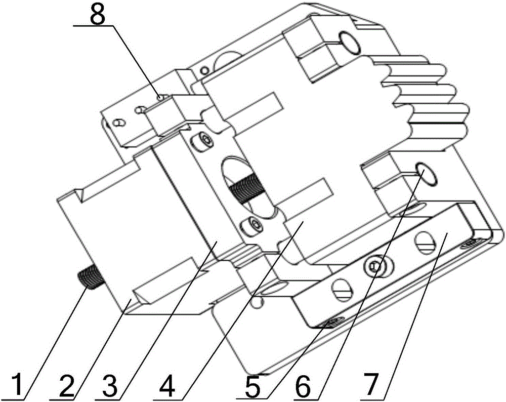
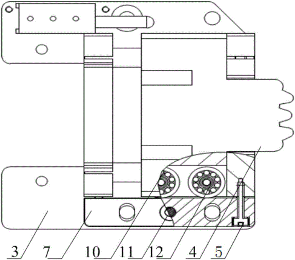
[0029] The rotating shaft locking device of the transmission mechanism of the present invention controls the movement of the locking block 4 by using a linear motor with a self-locking function, and relies on the front teeth of the locking block 4 to be inserted into the locking gear connected to the rotating shaft so that the two teeth mesh with each other. Realize the locking of the rotating shaft, so as to realize the locking of the transmission mechanism such as the turntable connected with the rotating shaft; when unlocking, control the motor to disengage the front teeth of the locking mechanism from the locking gear, and rely on the screw nut pair of the linear stepping motor Self-locking ability to maintain locking force and locking accuracy.

[0030] Specifically, such as figure 1 As...


PUM


Abstract

The invention discloses a rotating shaft locking device of a transmission mechanism. The rotating shaft locking device comprises a transmission locking device and a locking gear fixedly connected onto a rotating shaft of the transmission mechanism; the transmission locking device comprises a lead screw, a driving motor, a base, a locking block and guide rails which are parallelly fixed on the base; the two sides of the locking block sleeve the guide rails; one end of the locking block is provided with teeth meshed with the locking gear, and the other end of the locking block is connected with the driving motor which is fixed on the base through the lead screw; the driving motor drives the locking block to move along the guide rails to be meshed with the locking gear for locking or to be separated from the locking gear for unlocking through the lead screw; the driving motor is utilized for providing power for the locking block to ensure the insertion and the separation of the teeth; the automatic locking function of the rotating shaft is effectively solved; the locking force can be set by controlling the rotation speed of the driving motor and the backoff amount after locking; the maintenance of a locking load is realized through the self-locking ability of a screw-nut pair; the locking reliability is high; and the assembly is convenient.

Description

technical field [0001] The invention relates to a locking mechanism of electromechanical transmission equipment, in particular to a rotating shaft locking device of a transmission mechanism. Background technique [0002] The shaft locking of existing transmission mechanisms such as turntables mainly relies on the self-locking function of its transmission components, such as the self-locking property of worm gears or electromagnetic clutches. Using worm gears as self-locking mechanisms for rotating shafts requires self-locking of worm gears and worms. The lock function causes the disadvantage of low efficiency of the transmission chain and the high power of the driving motor. Using an electromagnetic clutch as a locking mechanism has the problems of large volume and large magnetic interference of the electromagnet to the work of the precision parts of the turntable. Contents of the invention [0003] Aiming at the problems existing in the prior art, the present invention pr...

Claims


Application Information

Patent Timeline
Patent Type & Authority Applications(China)
IPC IPC(8): F16C1/02H02K7/00
Inventor 魏浩东马志伟李忠涛龚荣文张强
Owner NO 771 INST OF NO 9 RES INST CHINA AEROSPACE SCI & TECH
Why Eureka
Try Eureka