Mechanical arm

A technology of manipulators and arms, applied in the field of manipulators, can solve problems such as substrate drop and product yield reduction

Active Publication Date: 2015-12-16
BOE TECH GRP CO LTD +1
View PDF7 Cites 3 Cited by
  • Summary
  • Abstract
  • Description
  • Claims
  • Application Information

AI Technical Summary

Problems solved by technology

[0005] The inventors found that the existing manipulators have the following problems in the process of taking and placing substrates. On the one hand, during the rotation process of the first support structure 11, the substrate has the risk of falling from the arm 14, and the yield rate of the product is reduced

Method used


Image

  • Mechanical arm
  • Mechanical arm
  • Mechanical arm

Examples


Embodiment Construction

[0033] The following will clearly and completely describe the technical solutions in the embodiments of the present invention with reference to the accompanying drawings in the embodiments of the present invention. Obviously, the described embodiments are only some, not all, embodiments of the present invention. Based on the embodiments of the present invention, all other embodiments obtained by persons of ordinary skill in the art without making creative efforts belong to the protection scope of the present invention.

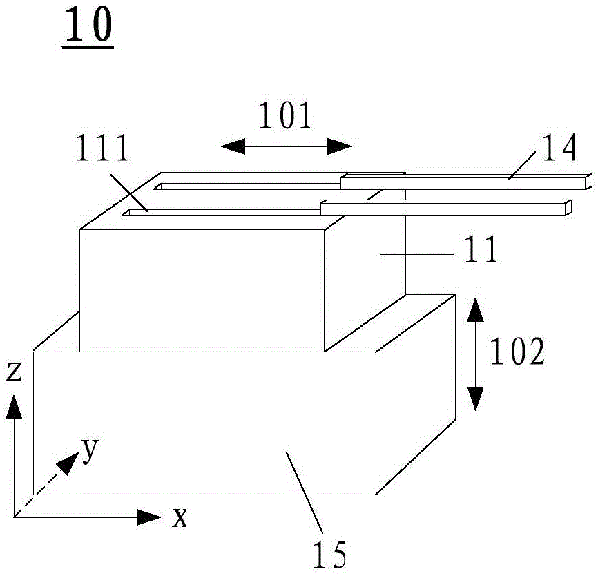
[0034] An embodiment of the present invention provides a manipulator, which is installed between the first chamber and the second chamber of the vacuum reaction equipment, and is used to move the plates in the first chamber to the second chamber; image 3 As shown, the manipulator 10 includes: a first support structure 11, the first support structure 11 is provided with a track 111 along the first direction 101 on the horizontal plane, and the first chamber and...


PUM


Abstract

The invention provides a mechanical arm, and relates to the field of automation. The mechanical arm solves the problems that when a conventional mechanical arm takes and places boards, the conventional mechanical arm needs to rotate, so that the occupied space is large, and the rate of qualified products is reduced. The mechanical arm is mounted between a first chamber and a second chamber of vacuum reaction equipment, and used for moving the boards in the first chamber to the second chamber. The mechanical arm comprises a first supporting structure, arms and a vertically-moving mechanism, wherein railways in the first direction of a horizontal plane are formed in the first supporting structure; the first chamber and the second chamber are respectively positioned at two opposite ends of the railways; the arms are mounted on the first mounting structure and used for bearing the boards; the arms can move along the railways; the first supporting structure and the arms are mounted on the vertically-moving mechanism, and the first supporting structure and the arms can be driven by the vertically-moving mechanism to move in the vertical direction.

Description

technical field [0001] The invention relates to the field of automation, in particular to a manipulator. Background technique [0002] At present, in the production process of TFT-LCD (ThinFilmTransistor-LiquidCrystalDisplay, thin film transistor liquid crystal display), the vacuum reaction equipment used such as figure 1 As shown, it includes a vacuum transition chamber, a transfer chamber and at least one reaction chamber, wherein the transfer chamber is connected to the vacuum transition chamber and each reaction chamber respectively. Wherein, a manipulator is provided in the transfer chamber, and the manipulator can realize the turnover of plate-shaped products such as substrates between the vacuum transition chamber and each reaction chamber. [0003] Such as figure 2 As shown, the existing manipulator 10 includes: a first support structure 11, a second support structure 12, a third support structure 13 and an arm 14; wherein, the first support structure 11 can be on...

Claims


Application Information

Patent Timeline
Patent Type & Authority Applications(China)
IPC IPC(8): B65G47/90B65G49/06
CPCH01L21/67733H01L21/67196H01L21/67742H01L21/67748
Inventor 李锦坤郭国明顾楠轩侯健刘书雨刘敏郝西魁
Owner BOE TECH GRP CO LTD
Why Eureka
Try Eureka