
Blade gap adjusting and locking mechanism for plate shearing machine

A technology of locking mechanism and gap adjustment, which is applied in the direction of knives, shearing devices, metal processing equipment, etc. used in shearing machine devices, and can solve the problems of easy loosening of screws, inaccuracy, and uniformity of gap between upper and lower blades, etc., to achieve Avoid loose, simple structure effect

Inactive Publication Date: 2015-12-16
JIANGSU YAWEI MACHINE TOOL
View PDF0 Cites 1 Cited by
  • Summary
  • Abstract
  • Description
  • Claims
  • Application Information

AI Technical Summary

Problems solved by technology

[0003] The existing adjustment devices for the gap between the upper and lower blades of various shearing machines basically use the upper blade to adjust the gap between the upper and lower blades. Some also use the manual adjustment of the lower blade and then manually measure with a feeler gauge. However, this method is not accurate enough and requires workers to enter The measurement in the machine tool is less safe; the traditional locking mechanism of the lower tool seat is generally locked by screws, and the screws are easy to loosen, resulting in easy changes in the uniformity of the upper and lower blade gaps

Method used


Image

  • Blade gap adjusting and locking mechanism for plate shearing machine
  • Blade gap adjusting and locking mechanism for plate shearing machine
  • Blade gap adjusting and locking mechanism for plate shearing machine

Examples


Embodiment Construction

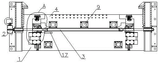
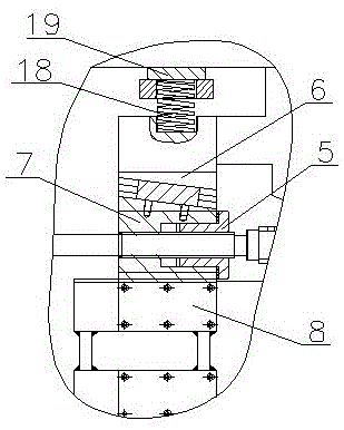
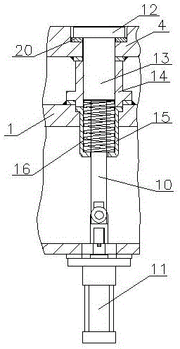
[0017] A blade clearance adjustment and locking mechanism of a shearing machine, comprising a reduction motor 2 installed on one side of a shearing machine frame 1, a screw rod 3 connected to the output end of the reduction motor 2, and a lower motor mounted on the frame 1 Knife holder 4, nuts 5 are sleeved at both ends of the screw rod 3, two fixed slanting blocks 6 are fixedly installed on the lower knife holder 4, and slanting blocks 7 are respectively sleeved on the outside of the two nuts 5. The block 7 is in close contact with the fixed slanting block 6, the horizontal side of the slanting block 7 matches the support block 8 installed on the frame 1, and the lower tool holder 4 is connected with the frame 1 through a locking mechanism 9; The locking mechanism 9 includes a connecting rod 10, the lower end of the connecting rod 10 is connected to the oil cylinder 11 installed on the frame 1, the upper end of the connecting rod 10 is provided with a pressing plate 12, and a ...


PUM


Abstract

The invention relates to a blade gap adjusting and locking mechanism for a plate shearing machine. The blade gap adjusting and locking mechanism comprises a speed reducing motor installed at one side of a rack of the plate shearing machine, a lead screw connected with the output end of the speed reducing motor, and a lower blade base installed on the rack. The two ends of the lead screw are sleeved with nuts. Two fixed inclining blocks are fixedly installed on the lower blade base. Each nut is sleeved with one inclining block. The inclining blocks make close contact with the fixed inclining blocks. The horizontal side faces of the inclining blocks are matched with supporting blocks installed on the rack. The lower blade base and the rack are connected through the locking mechanism. The blade gap adjusting and locking mechanism is simple in structure; the speed reducing motor drives the lead screw, the lead screw pushes and pulls the nuts, the nuts drive the inclining blocks to move left and right, and therefore the inclining blocks push the fixed inclining blocks to enable the lower blade base and a lower blade to move slightly; meanwhile, by means of the thrust effect of a compressing spring, it is ensured that the fixed inclining blocks and the inclining blocks keep a close contact state constantly, and the purpose of fine adjustment of a gap between upper blade and lower blade cutting edges is achieved.

Description

technical field [0001] The invention relates to a blade gap adjustment and locking mechanism of a shearing machine, which belongs to the technical field of shearing machine equipment. Background technique [0002] The shearing machine is used for the shearing of metal plates. The shearing power of the shearing machine comes from hydraulic transmission or mechanical transmission. When shearing the plate, the upper blade must be adjusted according to the shear strength of the sheared metal plate and the thickness of the metal plate. The gap between the mouth and the edge of the lower blade, and keep the gap uniform. The thicker the sheet metal and the higher the shear strength, the greater the gap between the upper and lower blade edges. When the shearing machine cuts the metal plate, the front end of the metal plate is sent to the stopper reference position of the shearing machine, and then the pressing device presses the metal plate on the back side of the cutting edge of t...

Claims


Application Information

Patent Timeline
Patent Type & Authority Applications(China)
IPC IPC(8): B23D35/00
Inventor 朱蔚杨建军潘恩海黄旸胡志达
Owner JIANGSU YAWEI MACHINE TOOL
Learn More