
Patsnap Eureka
For R&D, Patsnap Eureka makes reading and utilizing patents & technical documents easy.
Patsnap Eureka AIR
Designed for self-driven R&D workflows. Generate viable solutions, solve complex R&D challenges, empower your innovation with AI.

Patsnap Eureka Materials
Designed for material experts only. Revolutionize your material R&D, from search, analyze, to developing new materials.

TechResearch
Generate reliable direction feasibility study reports for your R&D in just a few steps.

TechSeek
Discover and master advanced knowledge NOW. Basics, ideas, possibilities, all at once.

TechMind
As an expert in R&D Theories, TechMind can generates customized viable solutions instantly.

TechRisk
Analyze your overall solution with one click, know your potential R&D risks in advance.

TechMonitor
Get weekly tech updates, stay abreast of the latest tech innovations and key insights.
Permanent magnet synchronous motor rotor and permanent magnet synchronous motor
A permanent magnet synchronous motor and rotor technology, which is applied in the direction of synchronous machine parts, magnetic circuit rotating parts, magnetic circuit shape/style/structure, etc., can solve high cogging torque, performance degradation of permanent magnet synchronous motor, air The problem of high harmonic content of load back EMF can be achieved to improve performance, optimize the waveform of air gap magnetic field, and reduce the effect of harmonic content
- Summary
- Abstract
- Description
- Claims
- Application Information
AI Technical Summary
Problems solved by technology
Method used
Image

Examples
Embodiment 1
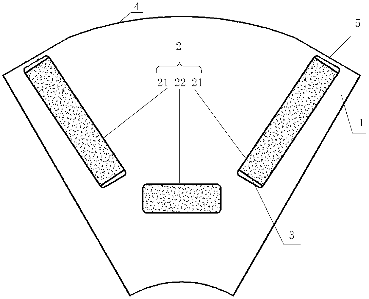
[0023] figure 1 It is a partial structural schematic diagram of the permanent magnet synchronous motor rotor according to Embodiment 1 of the present invention, as figure 1 As shown, the permanent magnet synchronous motor rotor includes: a rotor core 1 and a magnetic circuit assembly 2, wherein the magnetic circuit assembly 2 includes two tangential permanent magnets 21 distributed in the radial direction, and the tangential permanent magnets 21 are arranged in the permanent magnet slots 3, the same polarity of the two tangential permanent magnets 21 is opposite, a radial permanent magnet 22 is arranged between the two tangential permanent magnets 21 and near the inner side of the rotor core 1, and the radial permanent magnet 22 faces One side of the stator has the same polarity as the opposite side of the two tangential permanent magnets 21, and the radial cross-sectional shape of the rotor core 1 is composed of arcs 4 and straight lines 5, wherein the part close to the tange...
Embodiment 2
[0028] This embodiment is a supplementary description based on the first embodiment.
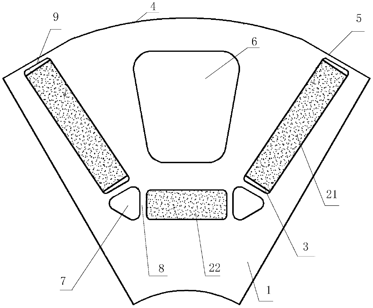
[0029] figure 2 It is a partial structural schematic diagram of the permanent magnet synchronous motor rotor according to Embodiment 2 of the present invention, as figure 2 As shown, the rotor of the permanent magnet synchronous motor also includes an auxiliary hole 6 , and the auxiliary hole 6 is arranged between two tangential permanent magnets 21 .
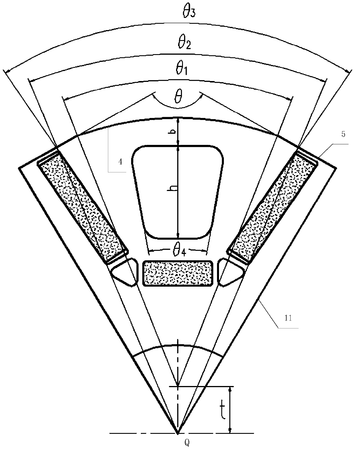
[0030] Further, the auxiliary hole 6 is trapezoidal. image 3 It is a schematic diagram of the positional relationship between the components of the permanent magnet synchronous motor rotor according to Embodiment 2 of the present invention, as image 3 As shown, by adjusting the height h of the trapezoid and the angle θ between the two waists 4 and the minimum distance b from the trapezoid to the surface of the rotor core 1 can optimize and adjust the air gap magnetic field waveform of the permanent magnet synchronous motor rotor, makin...
PUM
 Abstract
Description
Claims
Application Information
 - R&D Engineer
- R&D Manager
- IP Professional
- Industry Leading Data Capabilities
- Powerful AI technology
- Patent DNA Extraction
Browse by: Latest US Patents, China's latest patents, Technical Efficacy Thesaurus, Application Domain, Technology Topic, Popular Technical Reports.
© 2024 PatSnap. All rights reserved.Legal|Privacy policy|Modern Slavery Act Transparency Statement|Sitemap|About US| Contact US: help@patsnap.com