Eureka AIR delivers breakthrough ideas for toughest innovation challenges, trusted by R&D personnel around the world.

A pay-off rack with automatic speed adjustment

A technology of automatic speed regulation and pay-off frame, which is applied in the direction of thin material handling, delivery of filamentous materials, transportation and packaging, etc. The effect of excessive force on the line body

Active Publication Date: 2019-04-19
ANHUI HUANENG CABLE GRP
View PDF4 Cites 0 Cited by
  • Summary
  • Abstract
  • Description
  • Claims
  • Application Information

AI Technical Summary

Problems solved by technology

[0003] Based on the technical problems in the above-mentioned background technology, the present invention proposes a pay-off stand with automatic speed regulation to solve the problems of broken wires and slipping during the wire-drawing process

Method used


Image

  • A pay-off rack with automatic speed adjustment
  • A pay-off rack with automatic speed adjustment

Examples


Embodiment Construction

[0014] Below, the technical solution of the present invention will be described in detail through specific examples.

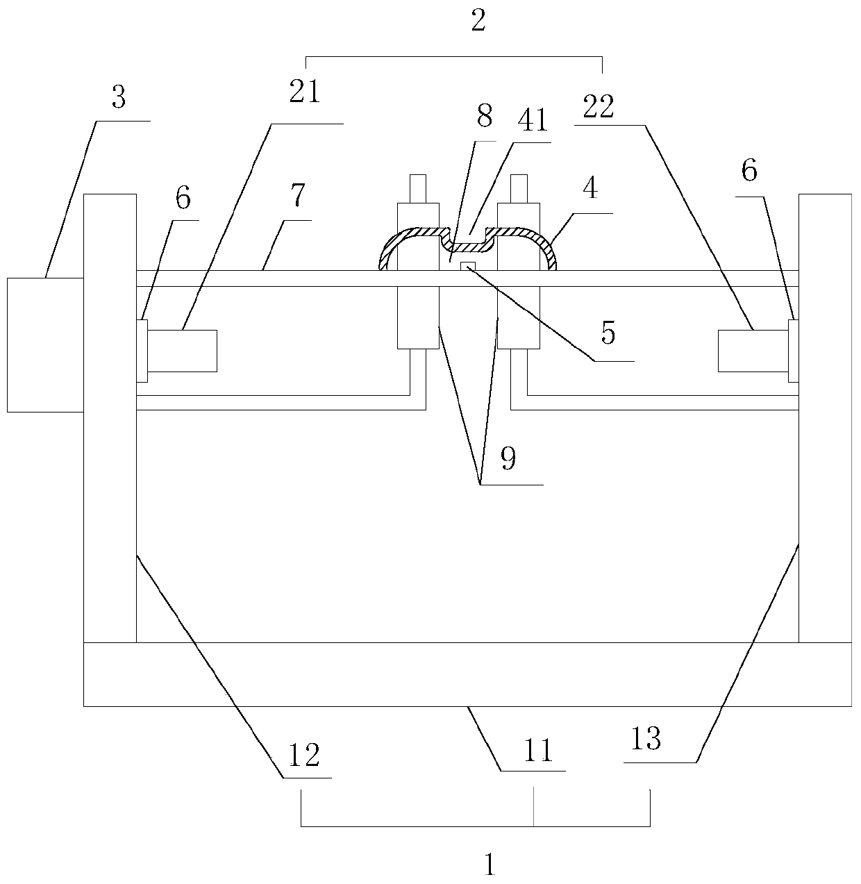
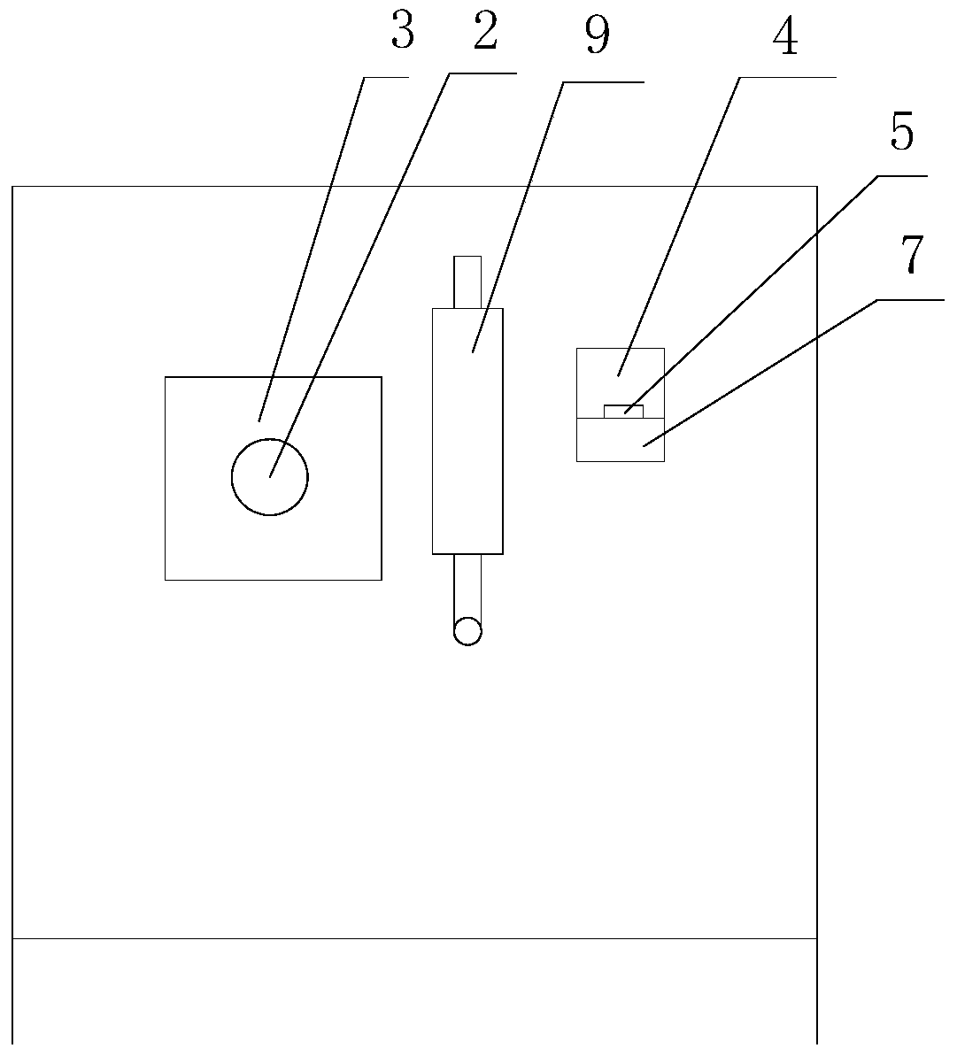
[0015] like Figure 1-2 as shown, figure 1 It is a structural schematic diagram of a pay-off rack with automatic speed regulation proposed by the present invention; figure 2 It is a position relation diagram of each component in an automatic speed-regulating pay-off stand proposed by the present invention.

[0016] refer to Figure 1-2 , a pay-off rack with automatic speed regulation proposed by the embodiment of the present invention, comprising: a bracket 1, a pay-off shaft 2, a motor 3, an elastic diaphragm 4 and a sensor 5, wherein: the bracket 1 includes a base 11 and is relatively arranged on The left fixed mount 12 and the right fixed mount 13 of base 11 both sides; The output shaft is connected; the driven shaft 22 is fixed on the right holder 13 through the bearing 6, and in the working state, the driven shaft 22 is connected with the driving sha...


PUM


Abstract

The invention discloses a pay-off rack capable of automatically regulating a speed. The pay-off rack comprises a support, a pay-off shaft, a motor, an elastic diaphragm and a sensor, wherein the pay-off shaft is fixed on the support through a bearing, and one end of the pay-off shaft is connected with an output shaft of the motor; a cross beam is arranged on the support and at one side of the pay-off direction of the pay-off shaft; a wiring groove for penetration of a wire body is pre-formed in the elastic diaphragm, the two sides of the elastic diaphragm are fixed on the cross beam respectively, and a gap is reserved between the inner circumferential surface of the elastic diaphragm and the cross beam to form a buffer cavity; and the sensor is arranged in the buffer cavity, located below the wiring groove, and connected with the motor. According to the pay-off rack disclosed by the invention, the problem of wire breakage or sliding-off of the wire body due to a too high or too low tensioning force is solved through adjustment of the motor for a pay-off speed, thus effectively increasing the processing efficiency of a cable.

Description

technical field [0001] The invention relates to the technical field of cable processing, in particular to a pay-off stand capable of automatic speed regulation. Background technique [0002] In the cable processing process, pay-off racks are often used to pay off semi-finished reels. Although the existing pay-off stand is controlled by a motor to actively pay off the wire, the motor cannot be adjusted in speed during work. Therefore, it is easy to cause the tension of the thread body to be too large or too small. When the tension force of the thread body is too large, the thread will break; and when the tension force of the thread body is too small, it will easily slip. Once the wire body breaks or slips, it needs to be shut down for maintenance and adjustment, which seriously affects the work efficiency. Contents of the invention [0003] Based on the technical problems in the above-mentioned background technology, the present invention proposes a pay-off stand with aut...

Claims


Application Information

Patent Timeline
Patent Type & Authority Patents(China)
IPC IPC(8): B65H59/38
Inventor 马俊香祝永林吴本健丁建新田兆云
Owner ANHUI HUANENG CABLE GRP
Why Eureka
Eureka Blog
Learn More