
Medium and low speed magnetic levitation train air gas detection system and method

A technology for maglev trains and detection systems, applied in electric vehicles, measuring devices, vehicle components, etc., can solve the problem of inability to reflect the gap between linear motors and rails, electromagnets and rails, inconvenience for measurement personnel to measure and operate, and the impact of detection results is relatively high. large problems, to achieve the effect of simple structure, reduced labor intensity, and high degree of automation

Active Publication Date: 2015-12-09
NAT UNIV OF DEFENSE TECH
View PDF6 Cites 9 Cited by
  • Summary
  • Abstract
  • Description
  • Claims
  • Application Information

AI Technical Summary

Problems solved by technology

When the train is suspended, because the electromagnet has a strong magnetic field, it is not convenient for the measurement personnel to perform measurement operations; and the electromagnet is close to the high-voltage current supply rail, which is very unfavorable for the safety of the measurement personnel. Manual Measurement of Electromagnet Air Gap
The above detection process is usually carried out by manual measurement on the loading platform. The detection equipment is too simple, the detection process is long, and the detection results are greatly affected by human factors. Therefore, there are problems such as poor detection accuracy, poor repeatability, and low efficiency.
Moreover, this detection method can only measure a few data points, and cannot reflect the gap between the entire linear motor and the track, and the electromagnet and the track.

Method used


Image

  • Medium and low speed magnetic levitation train air gas detection system and method
  • Medium and low speed magnetic levitation train air gas detection system and method
  • Medium and low speed magnetic levitation train air gas detection system and method

Examples


Embodiment Construction

[0026] In order to enable those skilled in the art to better understand the technical solutions of the present invention, the present invention will be further described in detail below in conjunction with the accompanying drawings.

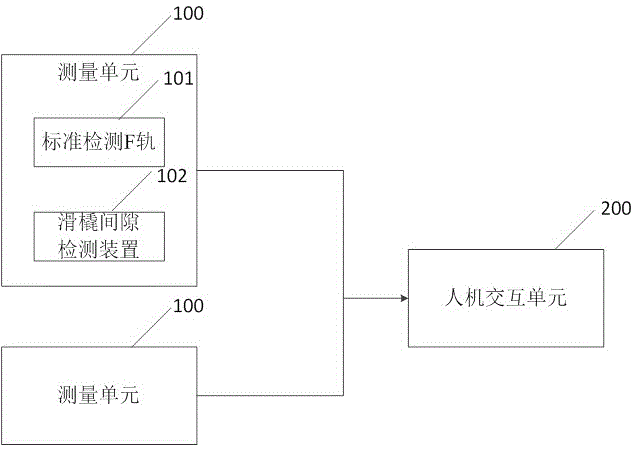
[0027] refer to Figure 1 to Figure 3 , figure 1 It is the structural block diagram of the air gap detection system of the medium and low speed maglev train of the present invention, figure 2 It is an installation schematic diagram of an air gap detection system for a medium-low speed maglev train of the present invention; image 3 It is a structural schematic diagram of a suspension frame of a medium-low speed maglev train.

[0028] The air gap detection system for medium and low-speed maglev trains of the present invention includes a measuring unit 100 for measuring the gap between the train track 2 and the suspension frame 3 of the medium-low speed maglev train. The measuring unit 100 includes a standard detection F rail 101, and the standa...


PUM


Abstract

The invention provides a medium and low speed magnetic levitation train air gas detection system and method. The medium and low speed magnetic levitation train air gas detection system comprises a measurement unit used for detecting the gap between the train rail and a medium and low speed magnetic levitation train suspension frame. The measurement unit comprises a standard detection rail F. The standard detection rail F is arranged in the middle of the medium and low speed magnetic levitation train rail and fixed to rail sleepers through fastening pieces. At least one sensor is arranged in the magnetic pole of the standard detection rail F. The gap between the standard detection rail F and the medium and low speed magnetic levitation train suspension frame is detected through the sensors, and the gap between the magnetic levitation train rail and the train suspension frame can be detected when a train runs. The medium and low speed magnetic levitation train air gas detection system and method have the advantages of being high in detection accuracy, simple in structure, convenient to operate and high in automation degree, the measurement accuracy is further improved, and safe running of the train is effectively ensured. Operators can conduct control through a man-machine interaction unit, and can know the state of the train when being far away from the train.

Description

technical field [0001] The invention relates to the technical field of medium and low speed maglev trains, in particular to an air gap detection system and method for medium and low speed maglev trains. Background technique [0002] The running part of the medium and low speed maglev train is composed of multiple suspension frames, which are important components of the medium and low speed maglev train. The medium and low speed suspension frame is composed of left and right two independent suspension modules and an anti-roll decoupling mechanism. The left suspension module and the right suspension module have the same structure and are symmetrically arranged on the left and right rails. Institutional connections. The maglev train is pulled by a linear motor. One stage of the linear motor is installed on the suspension module, and the other stage is fixed on the guide rail and extends to the distance. When the primary is connected to AC, the electromagnet installed on the tr...

Claims


Application Information

Patent Timeline
IPC IPC(8): B60L13/06G01B11/14
Inventor 刘耀宗龚朴邓文熙向湘林
Owner NAT UNIV OF DEFENSE TECH
Learn More