
Ground microseism monitoring anisotropy speed model

A velocity model and anisotropic technology, applied in seismic signal processing and other directions, can solve problems such as low positioning accuracy, large amount of calculation, and unsatisfactory positioning accuracy

Active Publication Date: 2015-12-02
UNIV OF ELECTRONIC SCI & TECH OF CHINA
View PDF6 Cites 13 Cited by
  • Summary
  • Abstract
  • Description
  • Claims
  • Application Information

AI Technical Summary

Problems solved by technology

The Inglada algorithm is simple to implement and uses a single-layer velocity model, but because it is contrary to the horizontal layered velocity model between formations, the positioning accuracy is not high; the Geiger method uses a horizontal layered velocity model and iterative technology, so the positioning accuracy is better than that of Inglada. The algorithm has been improved; the grid search method is a basic global optimization algorithm. This method first needs to limit the range of solutions, set the size of the grid, divide the solution space into grids, and then use a grid as a unit Traverse the solution space to find the optimal solution in the solution space. This method depends on the determination of the solution space and the size of the grid that divides the solution space. The larger the grid, the lower the positioning accuracy, and the smaller the grid, the higher the positioning accuracy , but the calculation amount is also larger
[0006] Through the research, it is found that the propagation of P- and S-wave velocity in the formation medium is characterized by horizontal layers, that is, the velocity of P- and S-wave propagation is different in different layers. The existing microseismic positioning methods all use the horizontal layered velocity model positioning, but the positioning accuracy is not ideal, and there is still anisotropy in the propagation of formation velocity, that is, the propagation velocity of seismic waves from the same point will vary with the propagation direction.

Method used


Image

  • Ground microseism monitoring anisotropy speed model
  • Ground microseism monitoring anisotropy speed model
  • Ground microseism monitoring anisotropy speed model

Examples


Embodiment Construction

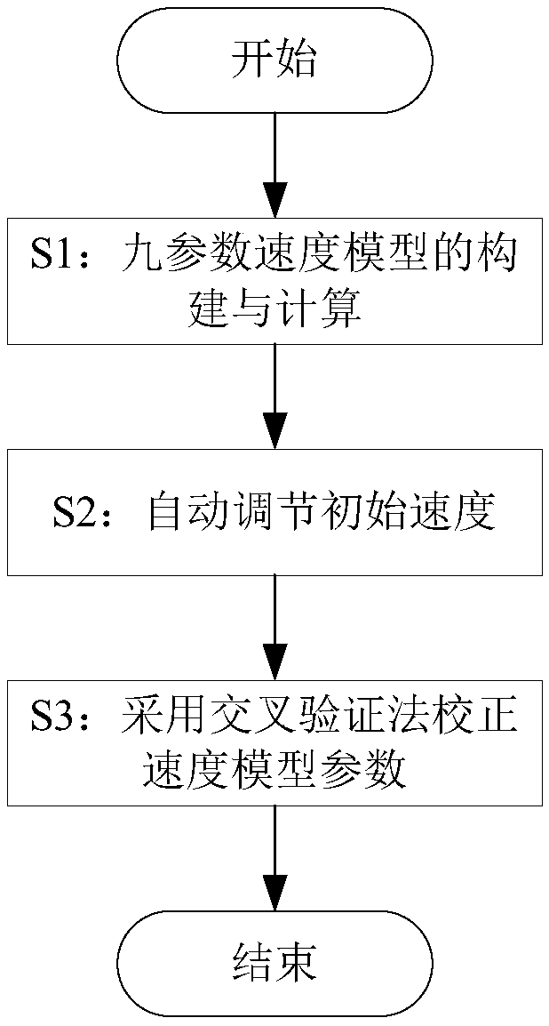
[0070] The present invention provides an anisotropic velocity model for ground microseismic monitoring and an automatic construction method of the model, mainly involving the construction and calculation of the nine-parameter velocity model S1, automatic adjustment of the initial velocity S2, and correction of the velocity model parameters S3 by using the cross-validation method , the present invention will be described in further detail below in conjunction with the accompanying drawings and specific embodiments.

[0071] The flow chart of the automatic construction method of the ground microseismic monitoring anisotropic velocity model described in the present invention is as follows figure 1 As shown, it specifically includes the following steps:

[0072] S1: Construction and calculation of nine-parameter velocity model

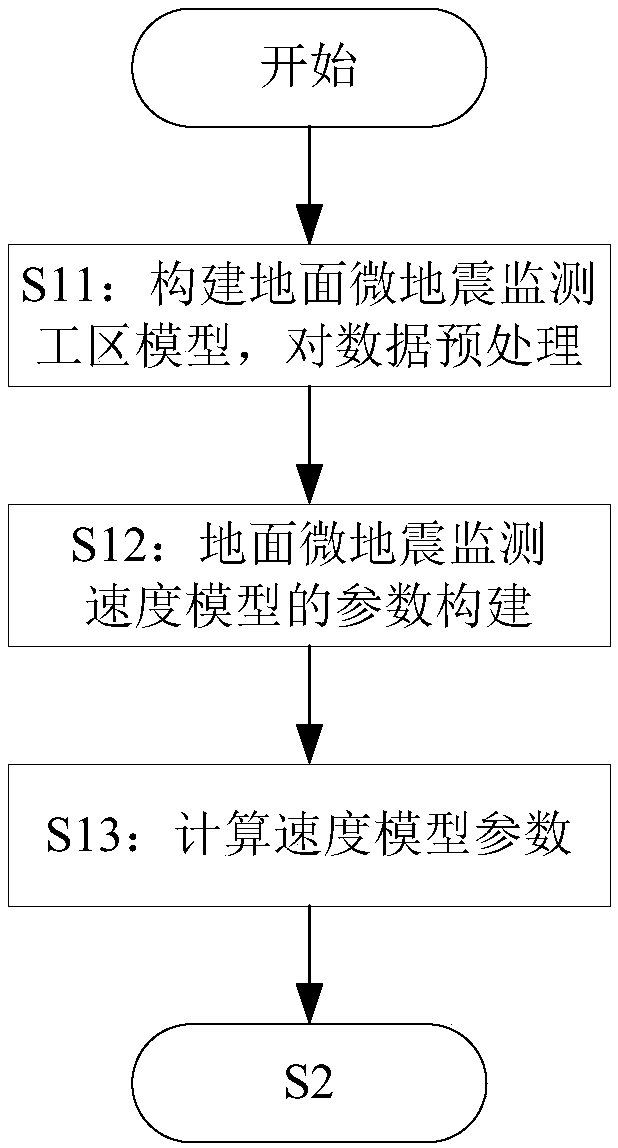
[0073] The construction and calculation process of the nine-parameter velocity model is as follows: figure 2 As shown, firstly, the work area model for...


PUM


Abstract

The invention provides a ground microseism monitoring anisotropy speed model and an automatic construction method thereof. The automatic construction method comprises: S1, constructing and calculating a nine-parameter speed model; S2, automatically regulating an initial speed; and S3, employing a cross validation method to calibrate speed model parameters. Compared with a traditional horizontal layer speed model, the speed model of the invention can embody the change trend of the speed with seismic wave propagation directions in a better way, and better simulate real seismic wave propagation, thereby building a more accurate speed model; through the speed model, positioning accuracy is higher; the speed model can automatically adjust an initial speed, thereby avoiding the trouble of artificially adjusting the initial speed, and determining the initial speed more efficiently; the speed model parameters are corrected by employing the cross validation method, the reciprocal value of positioning errors is used as a weight to linearly superpose speed model parameters of all sets, and corrected speed model parameters can improve positioning precision effectively.

Description

technical field [0001] The invention belongs to the field of microseismic monitoring, in particular to an anisotropic velocity model for ground microseismic monitoring. Background technique [0002] When some production activities occur, the stress around the original or newly created cracks in the rock will concentrate, and the strain energy will increase. When the external force increases to a certain extent, microscopic deformation will occur in the crack area, and part of the strain energy will be expressed as elastic waves. Forms are released, producing smaller earthquakes known as "microseismic". [0003] Earthquakes generally appear as clear pulses in seismic records. The stronger the microseismic event, the more obvious the pulse, and vice versa, the weaker the pulse. The occurrence of microseismic is complex in space and time, and its signal is easily affected by surrounding noise, and various media in the formation will absorb seismic waves and reduce their energy...

Claims


Application Information

Patent Timeline
IPC IPC(8): G01V1/28
Inventor 费高雷孙川胡光岷
Owner UNIV OF ELECTRONIC SCI & TECH OF CHINA
Learn More