
Insertion and expansion type ink injecting bottle

An ink filling bottle and bottle body technology, which is applied in the field of stationery, can solve the problems of ink spillage, waste and pollution, and high ink concentration, and achieve the effect of preventing spillage.

Active Publication Date: 2015-12-02
GUANGZHOU XINQI PATENT TECH EXTENSION SERVICE CO LTD +2
View PDF6 Cites 8 Cited by
  • Summary
  • Abstract
  • Description
  • Claims
  • Application Information

AI Technical Summary

Problems solved by technology

[0004] (1) Ink may overflow from the needle tube when the bottle cap is removed when the external temperature is high, which is likely to cause waste and pollution;
[0005] (2) During transportation, when the ink filling bottle is turned upside down or when the ink filling bottle is subjected to strong vibration, the ink in the bottle will overflow;
[0006] (3) When the ink pen is not used for a long time, due to the evaporation of part of the ink at the end of the pen, this will cause the ink concentration in the pen tank to be too high, which will easily cause blockage of the ink path and poor writing
However, the existing ink filling bottle cannot realize the above-mentioned function of returning ink and changing ink;
[0007] (4) If there is a lot of ink stored in the pen tank itself, when refilling ink, it will cause part of the ink to overflow, resulting in waste and pollution

Method used


Image

  • Insertion and expansion type ink injecting bottle
  • Insertion and expansion type ink injecting bottle
  • Insertion and expansion type ink injecting bottle

Examples


Embodiment Construction

[0023] The following will clearly and completely describe the technical solutions in the embodiments of the present invention with reference to the accompanying drawings in the embodiments of the present invention. Obviously, the described embodiments are only some, not all, embodiments of the present invention. Based on the embodiments of the present invention, all other embodiments obtained by persons of ordinary skill in the art without creative efforts fall within the protection scope of the present invention.

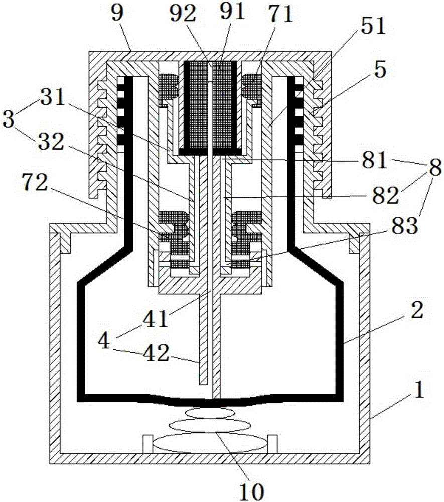
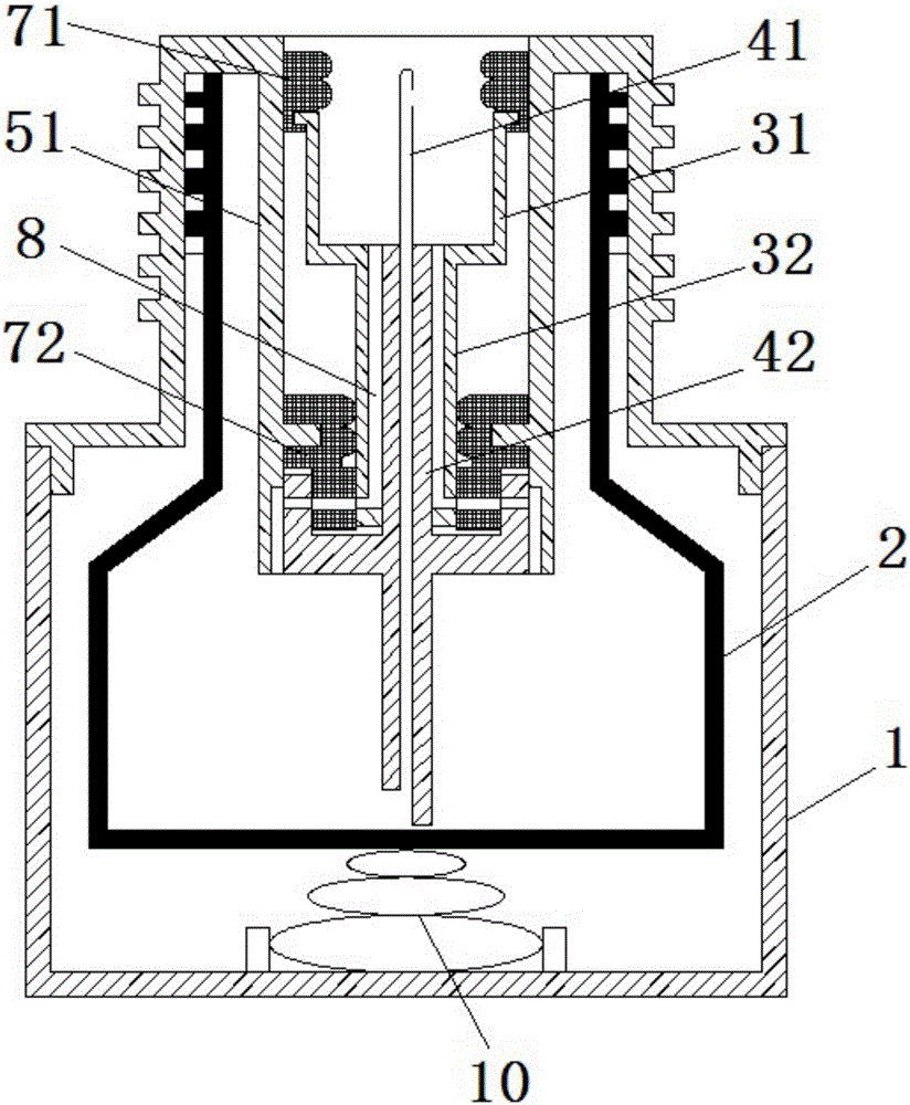
[0024] see in conjunction Figure 1 to Figure 3 As shown, an embodiment of the present invention is a kind of plug-in expansion ink bottle, which includes a bottle body 1, an inner tank 2, a needle seat 3 and a liquid injection tube 4; the bottle body 1 includes a bottleneck with a hollow cylinder 51 5; the liner 2 is arranged in the bottle body 1, and the bottom surface of the liner 2 is an elastic surface; the lower end of the hollow cylinder 51 extends above the...


PUM


Abstract

The invention provides an insertion and expansion type ink injecting bottle. The insertion and expansion type ink injecting bottle comprises a bottle body, a liner, a needle base and an injection pipe. The bottle body comprises a bottle neck provided with a hollow cylinder. The liner is arranged in the bottle body. The bottom surface of the liner is an elastic surface. The lower end of the hollow cylinder stretches into the upper portion of the liner. The needle base is arranged in the liner through the hollow cylinder and can move up and down in the hollow cylinder. The needle base comprises a supporting base and a sleeve base, wherein the supporting base is located on the upper portion of the needle base and allows a pen body to be inserted therein, and the sleeve base is located on the lower portion of the needle base and fixedly connected with the injection pipe in a sleeving mode. The upper end of the injection pipe is exposed out of the supporting base and communicated with the outside. The lower end of the injection pipe stretches to the bottom surface of the interior of the liner and communicated with the interior of the liner. A first sealing piece connected with the pen body in a sealing mode is fixedly arranged on the supporting base. A second sealing piece connected with the sleeve base in a sealing and sleeving mode is fixedly arranged on the inner wall of the hollow cylinder. At least one ventilation channel is formed in the needle base. By the adoption of the insertion and expansion type ink injecting bottle, ink returning in a pen barrel of an ink pen can be achieved before ink injection, and ink can be prevented from overflowing.

Description

technical field [0001] The invention relates to stationery, in particular to an ink bottle for plugging and expanding. Background technique [0002] At present, the fountain pen commonly used by people is an ink-absorbing fountain pen. After this fountain pen is inked, the nib part must be stained with ink, which needs to be wiped, which makes people feel inconvenient. In addition, when the ink in the ink bottle is full, the suction Ink can also easily stain the barrel. [0003] In addition, there is also a kind of ink-filling type ink bottle on the market, which is used to inject ink into the fountain pen liquid storage tube. After repeated tests by the applicant, the following problems still exist: [0004] (1) Ink may overflow from the needle tube when the bottle cap is removed when the external temperature is high, which is likely to cause waste and pollution; [0005] (2) During transportation, when the ink filling bottle is turned upside down or when the ink filling ...

Claims


Application Information

Patent Timeline
Patent Type & Authority Applications(China)
IPC IPC(8): B65D47/22B65D47/40B65D53/00
Inventor 章泽宏
Owner GUANGZHOU XINQI PATENT TECH EXTENSION SERVICE CO LTD
Learn More