


Quick Research
Generate reliable direction feasibility study reports for your R&D in just a few steps.

Technical Q&A
Discover and master advanced knowledge NOW. Basics, ideas, possibilities, all at once.

Find Solutions
As an expert in R&D theories, this can generate solutions to your technical problems instantly.

Evaluate Feasibility
Analyze your overall solution with one click, know your potential R&D risks in advance.

Monitor Landscape
Get weekly tech updates, stay abreast of the latest tech innovations and key insights.
Ultra-high-speed cleaning device for remotely piloted vehicle
A technology for cleaning devices and aircraft, applied to aircraft, cleaning methods and tools, cleaning methods using tools, etc., can solve problems such as cleaning the surface of photovoltaic panels, and achieve the effect of prolonging the time spent in the air
- Summary
- Abstract
- Description
- Claims
- Application Information
AI Technical Summary
Problems solved by technology
Method used
Image

Examples
Embodiment 1
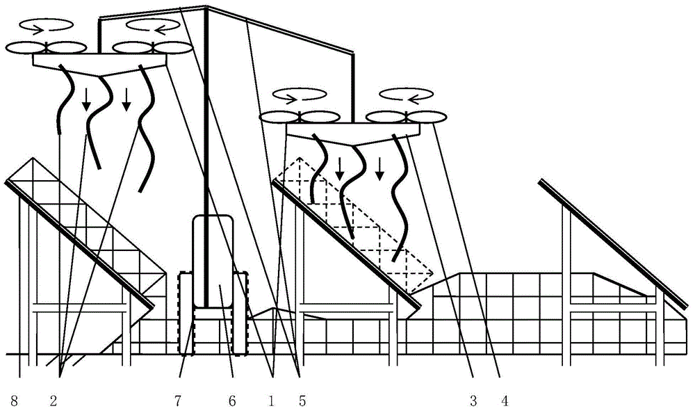
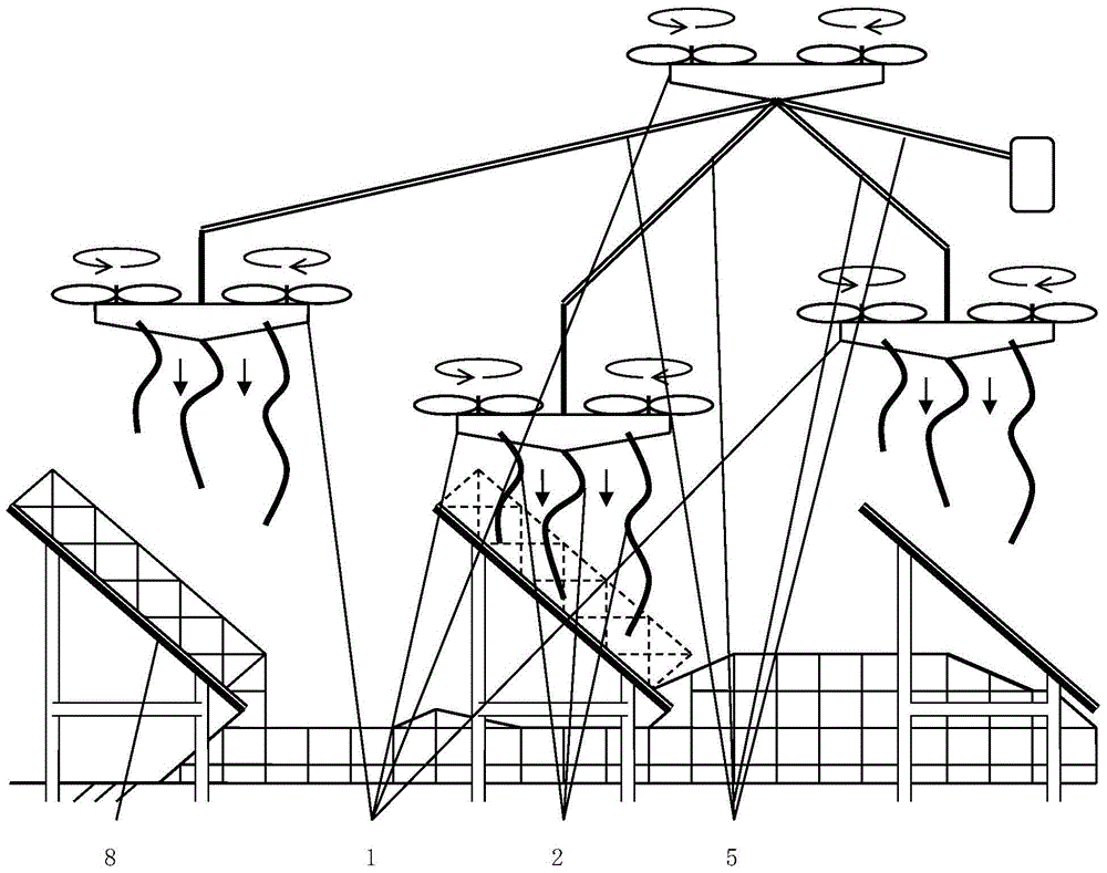
[0014] Embodiment 1, manufacture a remote-controlled aircraft ultra-high-speed cleaning device, including rotorcraft 1 and soft rope cloth strip 2; Rotorcraft 1 includes fuselage 3, several electric rotors 4, flight state computer control system and remote controller; flight state computer The control system includes a satellite positioning terminal, an accelerometer, a magnetometer, an air pressure sensor, a gyroscope and a communication module; the soft rope cloth strip 2 is suspended under the rotorcraft; the flexible rope includes nylon rope; the cloth strip includes canvas. A transmission line 5 is adopted, and the transmission line 5 is connected to the external power supply 6 and the rotorcraft 1, and continuously provides electric energy to the rotorcraft 1. In Embodiment 1, two rotorcraft 1 share an external power supply 6 . The external power supply 6 is carried on a logistics vehicle 7; the logistics vehicle 7 automatically drives through the passage between the pho...
Embodiment 3
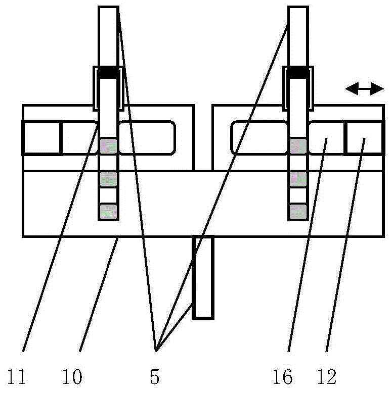
[0021] In embodiment 3, a three-terminal double-plug automatic connector is manufactured, which is connected in series between the upper rotorcraft of embodiment 2 and the power line of the lower rotorcraft. The automatic connector includes two sockets 10 , two plugs 11 and two automatic plug lockers 12 . The plug 10 has a concentric two-wire structure and is electrically connected to the power line 5 . For the specific content of the concentric two-wire structure, reference may be made to the prior art including the earphone plug of a mobile phone. These plugs are generally required to have close to zero insertion and extraction forces. Zero insertion force electrical plugs are already used on launch vehicles. The spring 14 is slidably fitted on the transmission line 5 . The automatic plug locker 12 is signal-connected with the flight state computer control system through an interface circuit. The automatic plug locker 12 includes a resisting block 15 and an electric depr...
PUM
 Abstract
Description
Claims
Application Information
 - R&D Engineer
- R&D Manager
- IP Professional
- Industry Leading Data Capabilities
- Powerful AI technology
- Patent DNA Extraction
Browse by: Latest US Patents, China's latest patents, Technical Efficacy Thesaurus, Application Domain, Technology Topic, Popular Technical Reports.
© 2024 PatSnap. All rights reserved.Legal|Privacy policy|Modern Slavery Act Transparency Statement|Sitemap|About US| Contact US: help@patsnap.com