
Power distribution automation cabinet and application thereof

A technology for automation cabinets and power distribution cabinets, which is applied to electrical components, pull-out switch cabinets, panel/switch station circuit devices, etc., and can solve problems such as the difficulty of unifying national grid standards

Active Publication Date: 2015-11-25
袁茂银
View PDF9 Cites 7 Cited by
  • Summary
  • Abstract
  • Description
  • Claims
  • Application Information

AI Technical Summary

Problems solved by technology

But at present, because the manufacturers of power equipment are different, the equipment produced is also different; but because the national grid standards are now unified, each manufacturer must transform the switchgears that have been put into use in accordance with the national grid standards , that is, to rearrange the wiring of all equipment in the outdoor switching station, which is equivalent to pulling each equipment back to the factory for re-production, which brings certain difficulties to the unification of the national grid standards and does not fundamentally solve the problem of the national grid. Transformation requirements for distribution network automation

Method used


Image

  • Power distribution automation cabinet and application thereof
  • Power distribution automation cabinet and application thereof
  • Power distribution automation cabinet and application thereof

Examples


Embodiment Construction

[0092] The present invention will be described in further detail and completely below in conjunction with the embodiments and accompanying drawings.

[0093] The types of equipment or components that are not described in detail in the following examples can be commercially available in the prior art, and only need to meet the functions of the distribution automation cabinet provided by the present invention, which is not a limitation of the present invention choose.

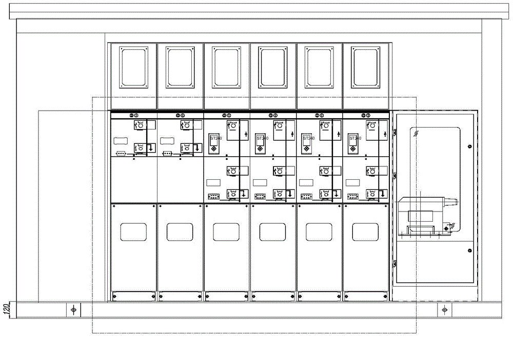
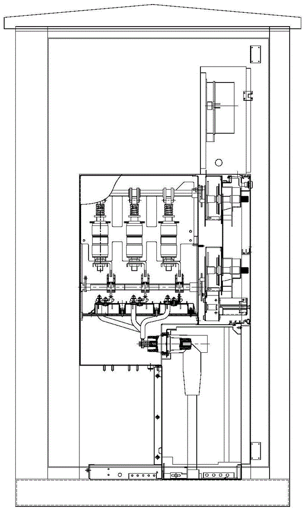
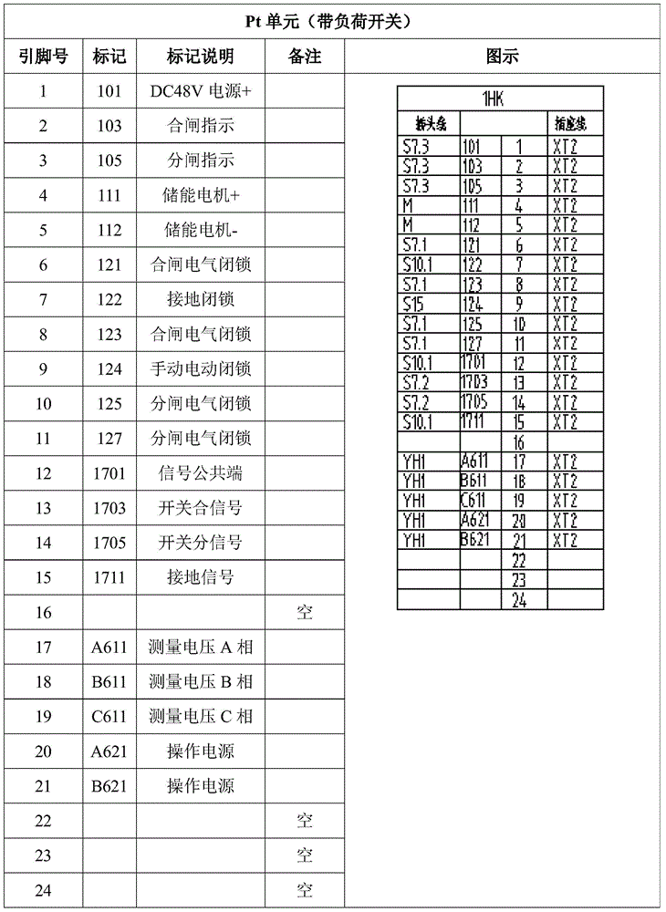
[0094] Figure 10-12 It is a schematic diagram of a preferred embodiment of the distribution automation cabinet provided by the present invention.

[0095] Such as Figure 10As shown: the power distribution automation cabinet 1 includes a first power distribution cabinet 11 and a second power distribution cabinet 12, the first power distribution cabinet 11 and the second power distribution cabinet 12 are composed of a cabinet body 13 and a plurality of unit modules that are movably connected 14 components, eac...


PUM


Abstract

The invention discloses a power distribution automation cabinet. The power distribution automation cabinet is composed of a cabinet body and a plurality of unit modules. Each unit module is movably connected with the cabinet body in a pulling-out manner and can be internally arranged in the cabinet body. Each unit module is provided with a plurality of secondary elements with different functions. The power distribution automation cabinet comprises a first power distribution cabinet and a second power distribution cabinet. The first power distribution cabinet is composed of a plurality of single-loop control protection unit modules. The second power distribution cabinet comprises a wiring terminal module, a DTU protection integration unit module, an ONU communication integration unit module and a power supply unit module. The first power distribution cabinet and the power distribution cabinet are electrically connected through the wiring terminal module. Compared with the prior art, the power distribution automation cabinet can be produced as a standard product, all function module equipment of the power distribution automation cabinet can also be produced and designed as standard products, and the power distribution automation cabinet can be matched with any kind of ring network cabinet group for usage; in addition, the safety problems of an outdoor switching station are solved, and the power supply continuity of the outdoor switching station is simultaneously improved.

Description

technical field [0001] The invention relates to a power distribution automation system, more specifically, to a power distribution automation cabinet, which belongs to the technical field of electrical equipment automation. Background technique [0002] The power system includes several main links of power generation, power transmission, power transformation, and power distribution, among which power distribution is a function that directly faces power users. In my country, the situation of "emphasis on power generation, light supply, and no use" has been formed for a long time. The distribution network system is seriously backward, resulting in high loss of residential wires, low voltage, and unreliable power supply, which has become a bottleneck in the power supply and consumption of the power system. In the early stage of power grid construction, more attention was paid to power generation and transmission, while power distribution and power consumption were often underes...

Claims


Application Information

Patent Timeline
IPC IPC(8): H02B11/173H02B11/02
CPCH02B1/056H02B1/20H02B1/24H02B1/308H02B1/36H02B1/565H02B11/133
Inventor 袁茂银
Owner 袁茂银
Learn More