
Abdominal exerciser with rotatable seat and tandem pulley features

Inactive Publication Date: 2012-03-08
E MISHAN & SONS
View PDF14 Cites 19 Cited by
  • Summary
  • Abstract
  • Description
  • Claims
  • Application Information

AI Technical Summary

Benefits of technology

[0005]An object of the invention is to provide an abdominal exerciser that has a base frame, a back frame pivotally mounted near a rear end of the base frame for movement between upright and recumbent positions, at least one back cushion connected to the back frame for supporting a user's back, a seat frame mounted for rotation on the base frame and a seat cushion fixed to the seat frame on which a user sits. A low friction journal bushing with a journal post rotatably mounted therein, is operatively connected between the base and seat frames for supporting the weight of the user. The bushing and post are about 30% to about 42% of the distance from a rear end of the seat cushion to the front end of the seat cushion so that the user's coccyx is substantially vertically aligned with the bushing and post when the user sits on the seat cushion and his or her back is resting against the back cushion. Arms at each side of the base frame have a pair of extensions connected to either the base or seat frame. Each arm has a U-shaped handhold lying in a plane extending at an acute angle of about 30 to about 80 degrees to the horizontal plane. A pair of pulleys is mounted for rotation near a rear end of the base frame and engages springs with resilient sleeves thereover, the springs being connected between the base and back frames for biasing the back frame toward the upright position.
[0006]A further object of the invention is to provide an abdominal exercise device that comprises: a base frame for lying in a horizontal plane on the floor, the base frame having a pair of side members and a cross member connected between the side members of the base frame; a back frame having a pair of side members pivotally mounted near respective rear ends of the respective side members of the base frame for movement between a forward upright position and a rearward recumbent position; a plurality of back cushions connected between and spaced along the side members of the back frame; an H-shaped seat frame having front and rear members and a cross member connected between the front and rear members; a seat cushion fixed to the seat frame and resting on the front, rear and cross members of the seat frame, the seat cushion having a front end and a rear end; a low friction journal bushing having a vertically extending bore and being connected to the cross member of one of the base and seat frames; a journal post connected to the cross member of the other of the base and seat frames and received for rotation in the low friction journal bushing so that the seat cushion may rotate with respect to the base frame, a support area of the cross member around the journal post and to which the journal post is connected, being in weight-bearing contact with the low friction journal bushing for supporting the weight of a user sitting on the seat cushion, the location of the low friction journal bushing and the journal post received therein, being from about 30% to about 42% of the distance from the rear end of the seat cushion to the front end of the seat cushion so that when a user is sitting on the seat cushion with the users back against the back cushions, the coccyx of the user is substantially vertically aligned with the low friction journal bushing and journal post received therein; an arm at each side of the base frame, each arm having a pair of extensions connected to one of the base frame and the seat frame, each arm including a U-shaped handhold lying in a plane that extends at an acute angle of about 30 degrees to about 80 degrees to the horizontal plane, with the handholds of the arms on opposite sides of the base frame extending outwardly from each other for increasing available room for a user sitting on the seat cushion, and access to the handholds by the user; a pulley mounted for rotation at each side of the base frame near a rear end of the base frame; a tension spring connected between the base frame and the back frame side members for biasing the back frame toward the forward upright position; and a resilient sleeve covering each spring, each resilient sleeve being engaged with one of the pulleys.

Problems solved by technology

Of these, the most common is the sit-up or crunch which, however is also known to place adverse pressure on the back and neck muscles.

Method used


Image

  • Abdominal exerciser with rotatable seat and tandem pulley features
  • Abdominal exerciser with rotatable seat and tandem pulley features
  • Abdominal exerciser with rotatable seat and tandem pulley features

Examples


Embodiment Construction

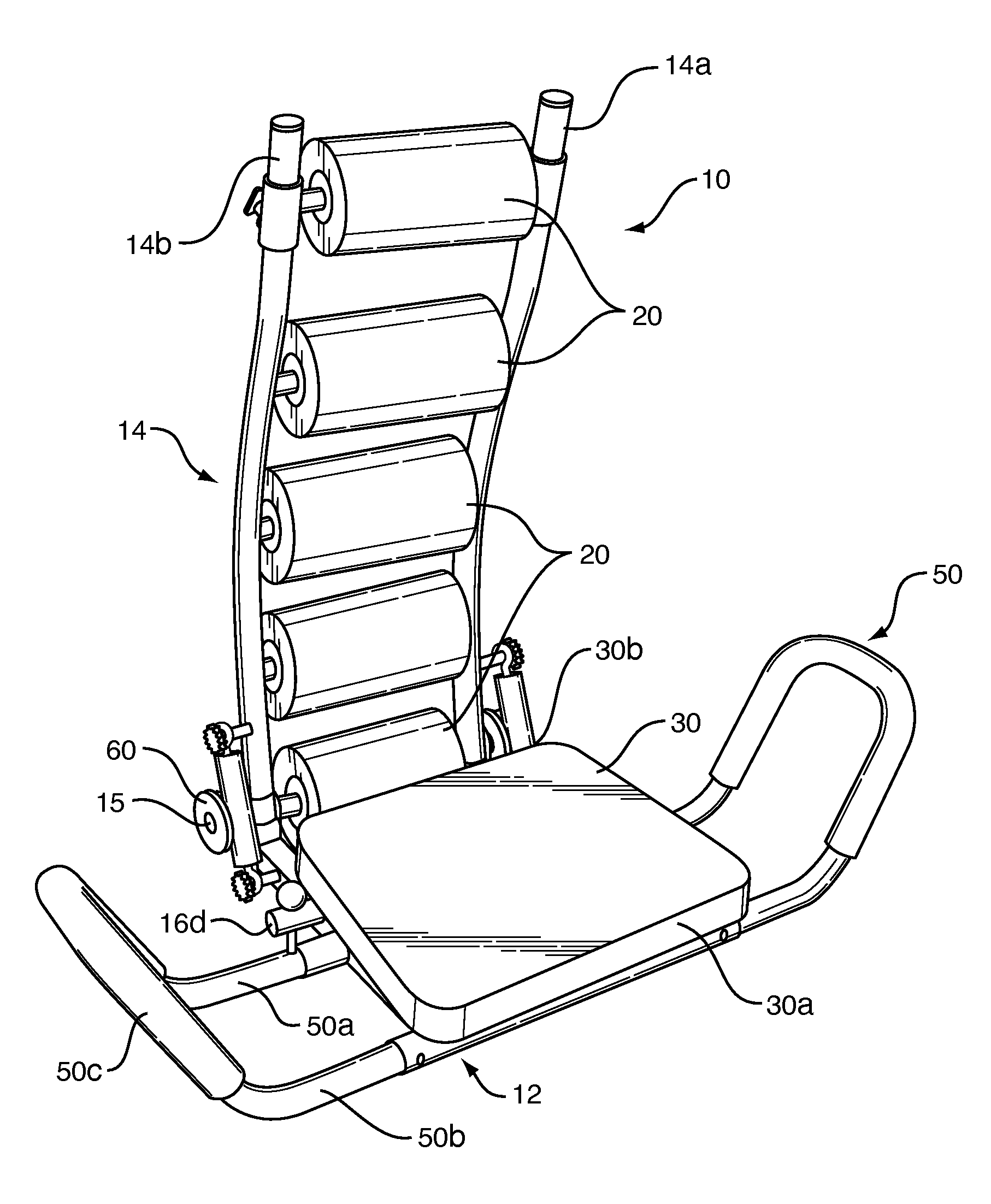
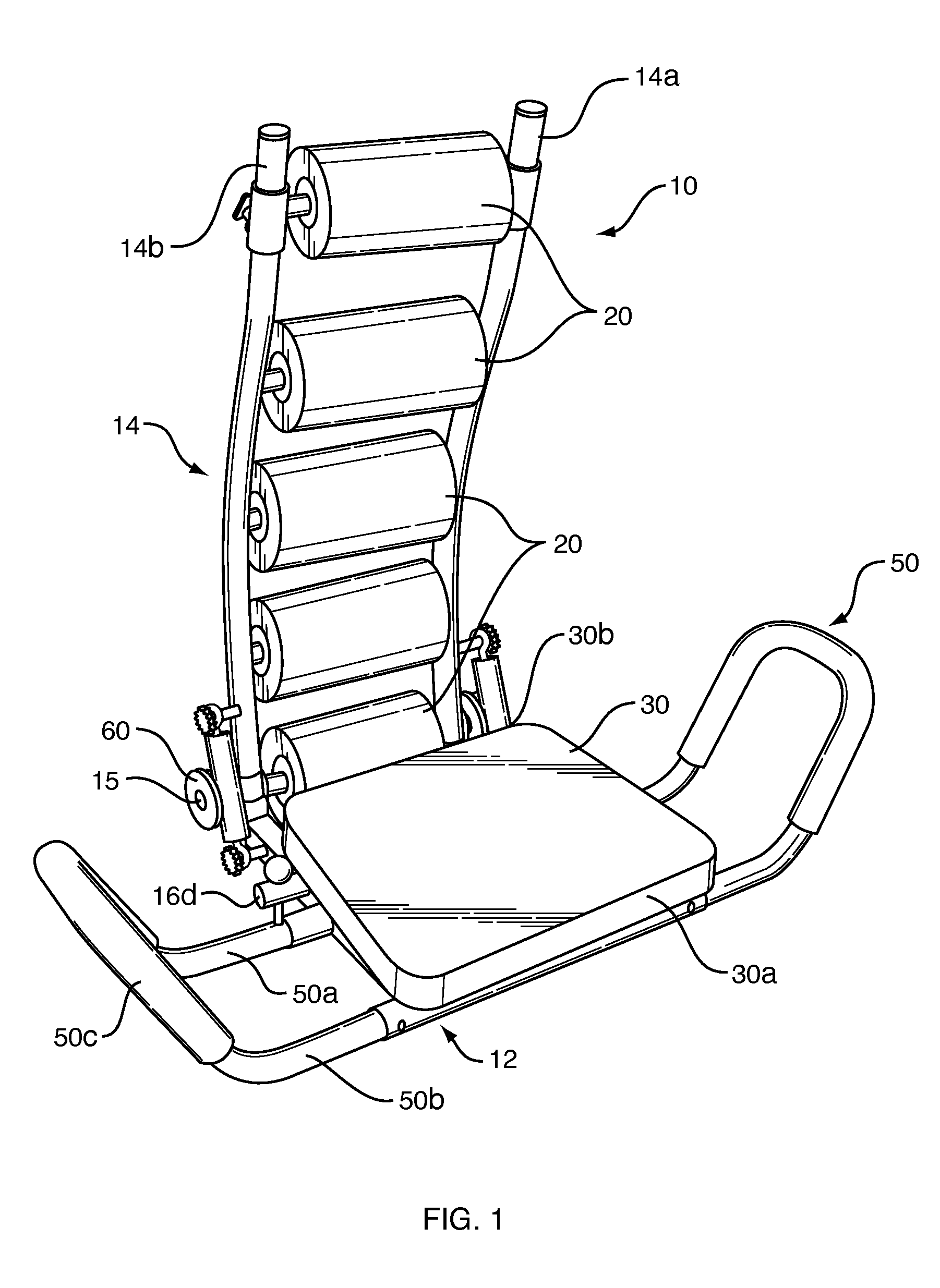
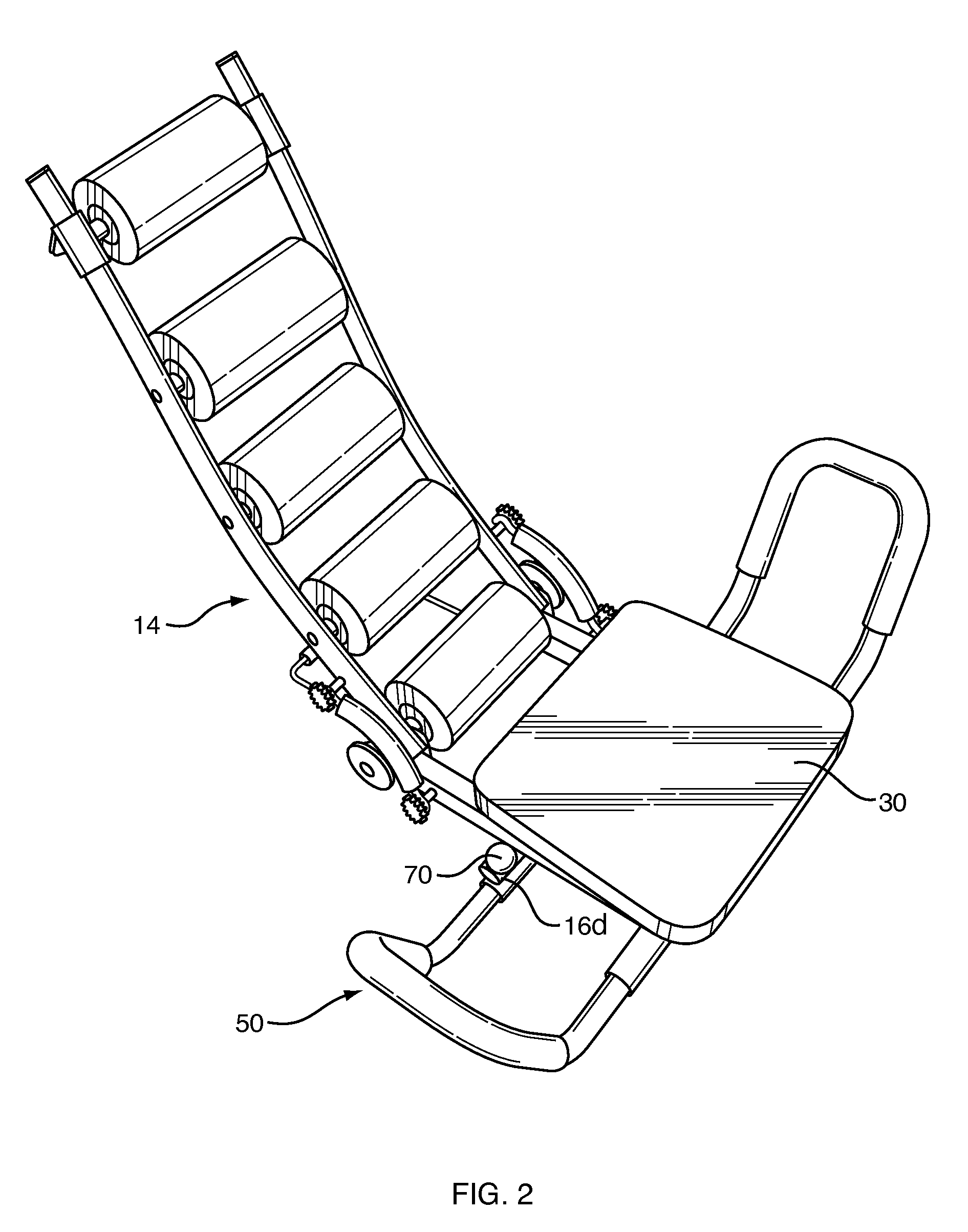
[0021]Referring now to the drawings, in which like reference numerals are used to refer to the same or similar elements, FIGS. 1 and 8 illustrate an abdominal exercise device 10 that comprises a base frame 12 for lying in a horizontal plane on the floor, the base frame having a pair of side members 12a and 12b and a cross member 12c connected, e.g. by welding, between the side members of the base frame. Members 12a, 12b and 12c and preferably square of rectangular cross-sectioned metal tubes. A back frame 14 having a pair of side members 14a and 14b is pivotally mounted on a pair of ears 13 at the top of, and near respective rear ends of the side members 12a and 12b of the base frame for movement between a forward upright position shown in FIG. 1, and a rearward recumbent position shown in FIG. 2. A bolt 15 extends through aligned holes in the pair of ears 13 on each side of base frame 12, to hold back frame side members 14a, 14b to the base frame, and to form the axle for one or tw...


PUM


Abstract

An abdominal exerciser has base and back frames pivotally mounted for movement between upright and recumbent positions, and a seat frame with cushion rotatable on the base frame. A low friction journal between the base and seat frames supports a user's weight. The journal is about 30 to 42% the distance from a rear end of the cushion to its front end so the user's coccyx is vertically aligned with the journal. Arms at each side of the base frame have a pair of extensions connected to either the base or seat frame, each with a U-shaped handhold lying in a plane at an acute angle of about 30 to 80 degrees to the horizontal. A pair of single pulleys or a pair of tandem pulleys are mounted near the rear of the base frame and are engaged by sleeve-covered springs for biasing the back frame toward the upright position.

Description

FIELD AND BACKGROUND OF THE INVENTION[0001]The present invention relates generally to the field of exercise devices, and in particular, to a new and useful abdominal exerciser with a seat and a back supporting structure.[0002]A wide variety of exercise devices and techniques are known for exercising the muscles of the stomach and back. Of these, the most common is the sit-up or crunch which, however is also known to place adverse pressure on the back and neck muscles.[0003]U.S. Pat. No. 7,381,171 and D581,471, which are both incorporated here by reference, disclose an abdominal exerciser co-invented by the inventors of the subject application. While effective for exercising the muscles of the stomach and back, the subject application discloses improvements that have been discovered as a result of use and understanding of the dynamics of the inventors' previous device.[0004]A need thus still remains for further improvements in abdominal exercise devices which enhance the exercising o...

Claims


Application Information

Patent Timeline
IPC IPC(8): A63B23/02
CPCA63B21/023A63B2210/50A63B21/0421A63B21/0435A63B21/055A63B21/1461A63B21/1492A63B21/1496A63B22/0087A63B22/14A63B23/0205A63B23/0211A63B23/0233A63B2023/003A63B2208/0238A63B21/026A63B21/4031A63B21/4049A63B21/4047A63B23/02A63B22/20
Inventor MISHAN, EDWARD I.MISHAN, STEVEN
Owner E MISHAN & SONS
Learn More