
Connector

A technology of connectors and plug-in connectors, which is applied in the direction of connection, parts of connection devices, electrical components, etc., to achieve a good fitting effect

Inactive Publication Date: 2015-11-25
JST MFG CO LTD
View PDF6 Cites 1 Cited by
  • Summary
  • Abstract
  • Description
  • Claims
  • Application Information

AI Technical Summary

Problems solved by technology

When the connector is installed on the device, in order to lead out the cable from the connector, it is necessary to leave a space in the direction in which it is drawn out. Therefore, if the fitting direction is the same as the direction in which the cable is drawn out, in addition to the size of the connector, due to the need The space for drawing out the cables is ensured, so the device itself with the connector is also enlarged in the fitting direction

Method used


Image

  • Connector
  • Connector
  • Connector

Examples


Embodiment Construction

[0026] Preferred embodiments of the present invention will be described below with reference to the drawings.

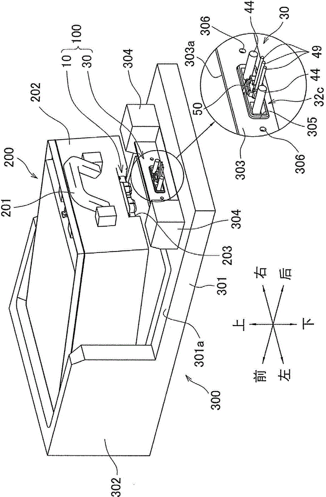
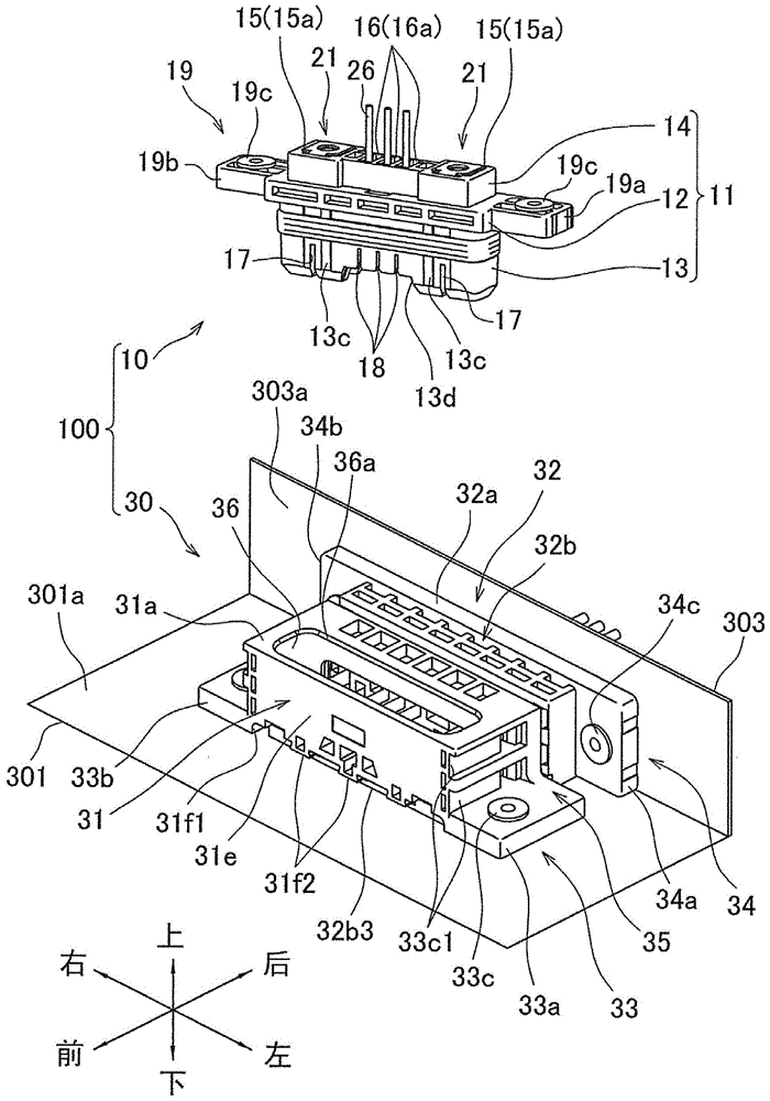
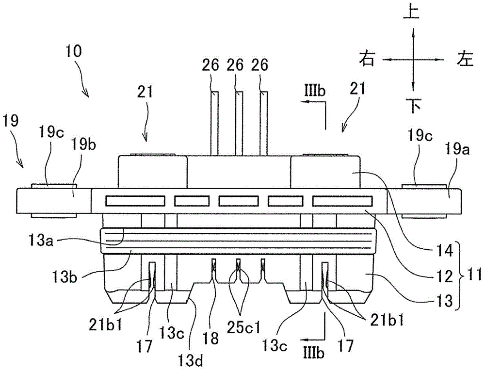
[0027] Such as figure 1 As shown, the connector 100 according to this embodiment is composed of a plug connector 10 and a base connector 30, the plug connector 10 is installed on the battery unit 200, and the base connector 30 is installed on the power supply device on which the battery unit 200 is installed. The installation part 300.

[0028] Here, the definition of the direction in this embodiment is demonstrated. Such as figure 1 As shown, the direction (first direction) perpendicular to the upper surface 301a (first mounting surface) of the support plate 301 of the mounting part 300, that is, the direction from the support plate 301 toward the connector 1 and the opposite direction are respectively defined as the upper direction. and below, the direction (second direction) perpendicular to the front surface 303a (second mounting surface) of the mounting plate...


PUM


Abstract

The invention relates to a connector. The connector is miniaturized in a fitting direction, and a contribution is made to miniaturization of a device, on which the connector is installed, in a fitting direction. The connector (100) is provided with a plug connector (10) and a base connector (30). The base connector (30) is provided with a first base housing (31), a second base housing (32), a first installation part (33), a second installation part (34) and an assembling part (35). The first installation part (33) enables the first base housing (31) to be installed in a manner that the first base housing (31) can move in the front-rear and left-right directions relative to the upper surface (301a). The second installation part (34) enables the second base housing (32) to be installed in a manner that the second base housing (32) can move in the left-right direction relative to the front surface (303a). The assembling part (35) enables the first base housing (31) and the second base housing (32) to be assembled in a manner that the first base housing (31) and the second base housing (32) can move in the front-rear and left-right directions.

Description

technical field [0001] The present invention relates to a connector having a base connector and a plug connector capable of mating with the base connector. Background technique [0002] Patent Document 1 describes a connector that can be fitted with a mating connector fixed to a substrate. The connector has: a fixed-side housing fixed to another substrate; and assembled so as to be slidable in the X direction A movable side housing on the fixed side housing; a plurality of fixed side contacts fixed to the fixed side housing; and a plurality of movable side contacts capable of respectively contacting the fixed side contacts accommodated in the movable side housing. head. In the mated state of the connector and the mating connector, there is a gap between the movable housing and the mating housing of the mating connector with respect to the Y direction (direction perpendicular to the X direction). Therefore, when the connector is mated with the mating connector, even if the ...

Claims


Application Information

Patent Timeline
IPC IPC(8): H01R12/91H01R12/71H01R13/502
Inventor 武田英次长绳政人
Owner JST MFG CO LTD
Learn More