Power supply system, linear control module and switch element control method

A technology of switching elements and linear control, which is applied in the direction of sequence/logic controller program control, electrical program control, control/regulation system, etc., and can solve problems such as DC power supply dips

Active Publication Date: 2015-11-25
CHICONY POWER TECH CO LTD
View PDF8 Cites 2 Cited by
  • Summary
  • Abstract
  • Description
  • Claims
  • Application Information

AI Technical Summary

Problems solved by technology

[0005] The purpose of the present invention is to provide a linear control module, the linear control module is electrically connected to a power supply device for supplying DC power, to solve the problem of DC power generation when the electronic system electrically connected to the power supply device is started. slump problem

Method used


Image

  • Power supply system, linear control module and switch element control method
  • Power supply system, linear control module and switch element control method
  • Power supply system, linear control module and switch element control method

Examples


Embodiment Construction

[0057] The above and additional objects, features and advantages of the disclosure of the present invention will be better understood through the following illustrative and non-limiting detailed description of preferred embodiments of the disclosure with reference to the accompanying drawings.

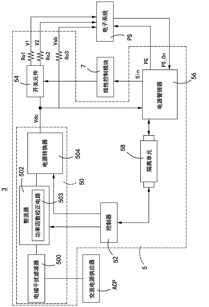
[0058] Cooperate with reference image 3 , a circuit block diagram of the power supply system of the present invention. The power supply system 3 includes a power supply device 5 and a linear control module 7 . The linear control module 7 is used to control the working state of a switch element 54 of the power supply device 5 .

[0059] The power supply device 5 is electrically connected between an AC power supply ACP and an electronic system PS for receiving the AC power output by the AC power supply ACP, and converting the AC power to the electronic system PS.

[0060] The power supply device 5 includes an AC / DC power conversion module 50, a controller 52, a switch element 54, a po...


PUM


Abstract

The invention discloses a power supply system, a linear control module and a switch element control method. The linear control module is electrically connected to a power supply device. The power supply device comprises an AC / DC power supply converting module, a switch element, a control signal output end, a main power supply output end and a standby power supply output end. The AC / DC power supply converting module has an electric power output end. The switch element is electrically connected with the electric power output end of the AC / DC power supply converting module and the main power supply output end. The standby power supply output end is electrically connected with the electric power output end of the AC / DC power supply converting module. The linear control module comprises a control switch, a first resistor, a capacitor and a second resistor. The control switch is electrically connected with the control signal output end. The first resistor is electrically connected with the control switch. The capacitor is electrically connected with the electric power output end of the AC / DC power supply converting module and the first resistor. The second resistor is electrically connected with the switch element, the first resistor and the capacitor.

Description

technical field [0001] The present invention relates to a power supply system, and in particular to a power supply system with low standby power consumption. Background technique [0002] Cooperate with reference figure 1 , is the circuit diagram of the existing switch control circuit. The switch control circuit 1 is electrically connected between a DC power VDC and a switch element 10 , and the switch control circuit 1 is used to control the switch element 10 to be turned on or off, and then determine whether the DC power VDC is connected to an electronic system PS. Wherein, the electronic system PS is electrically connected to the drain of the switch element 10 through the output resistors Ro1 and Ro2, and the terminals connected between the electronic system PS and the output resistors Ro1 and Ro2 are defined as power output terminals Vo1 and Vo2. [0003] The switch control circuit 1 includes a sense resistor RS, a control switch Q, a resistor R and a capacitor C. One...

Claims


Application Information

Patent Timeline
IPC IPC(8): G05B19/04
CPCG05B19/04G05F1/70
Inventor 汪子鸿李正雄萧正昌
Owner CHICONY POWER TECH CO LTD
Why Eureka
Try Eureka