
3D display device and control method thereof

A technology of a display device and a control method, applied in the field of 3D display, can solve problems such as affecting the viewing effect of 3D display, dizziness of human eyes, and even vomiting, and achieve the effect of improving viewing effect and comfort, light and thin structure, and simple and comfortable structure.

Inactive Publication Date: 2015-11-25
BOE TECH GRP CO LTD +1
View PDF6 Cites 39 Cited by
  • Summary
  • Abstract
  • Description
  • Claims
  • Application Information

AI Technical Summary

Problems solved by technology

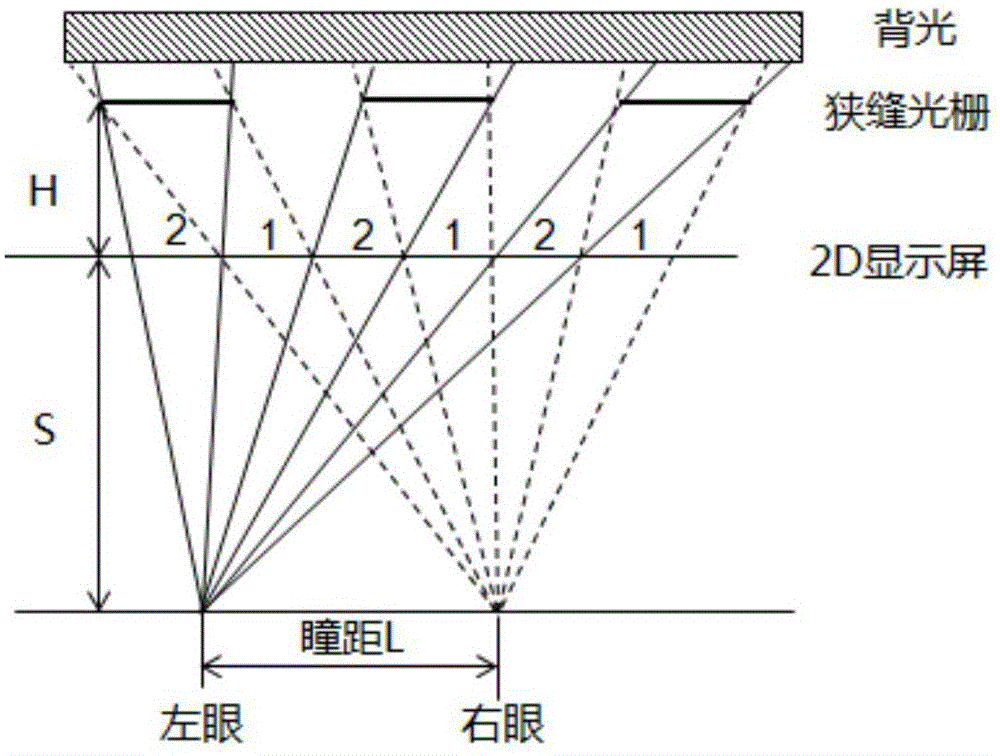
[0005] figure 2 It is a schematic diagram of the generation principle of the 3D dead zone in the prior art. When the viewer moves from the position shown on the left to the position shown on the right, if the moving distance of the human eye is exactly equal to the interpupillary distance, the left eye of the viewer moves to the original right eye viewing position, the right eye moves to the original left eye viewing position, causing the viewer's left eye to see the video on the display screen figure 2 screen, the right eye sees the video in the display figure 1 At this time, the human eye is in the dead zone of 3D viewing, that is, the left eye sees the picture that the right eye should see, and the right eye sees the picture that the left eye should see, and the human eye will feel dizzy or even vomit, seriously affecting the Viewing effect of 3D display

Method used


Image

  • 3D display device and control method thereof
  • 3D display device and control method thereof
  • 3D display device and control method thereof

Examples


Embodiment 1

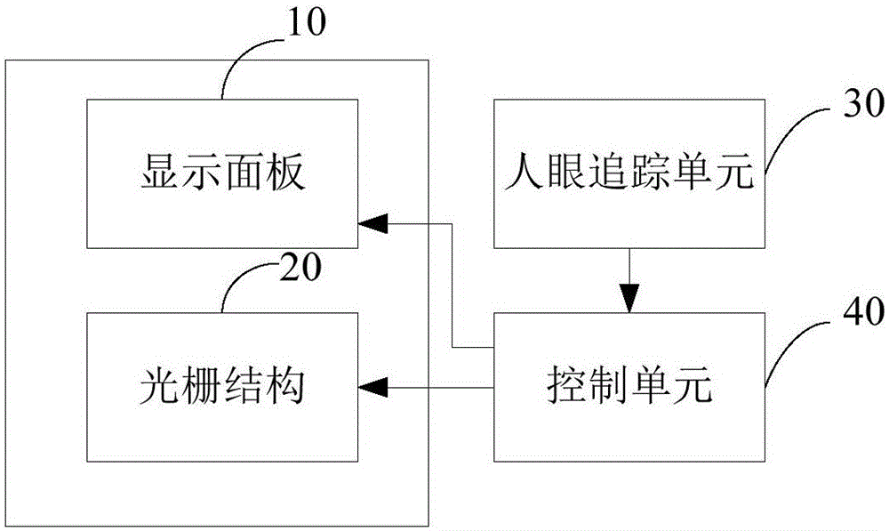
[0044] This embodiment provides a 3D display device, such as image 3 As shown, the 3D display device includes a display panel 10 for displaying images and a grating structure 20 that cooperates with the display panel 10 to form a 3D display effect. The raster, 3D display device also includes:

[0045] A human eye tracking unit 30 for obtaining the position of the viewer's human eyes;

[0046] It is connected with the human eye tracking unit, and is used to control the grating to switch between the light-transmitting state and the light-proof state according to the position of the viewer's human eye, so that the left eye of the viewer can see the first view on the display panel through the grating structure, A control unit 40 for making the viewer's right eye view the second view on the display panel through the grating structure.

[0047] In this embodiment, the human eye tracking unit acquires the position of the viewer's human eye, and the control unit controls the state of...

Embodiment 2

[0059] This embodiment also provides a method for controlling a 3D display device. The 3D display device includes a display panel for displaying images and a grating structure that cooperates with the display panel to form a 3D display effect. Gratings that switch between opaque states, such as Figure 4 As shown, the control method includes:

[0060] Step 201: Obtain the position of the human eyes of the viewer;

[0061] Step 202: Control the grating to switch between the light-transmitting state and the opaque state according to the position of the viewer's human eyes, so that the viewer's left eye can see the first view on the display panel through the grating structure, and the viewer's right eye can see the first view on the display panel. A second view on the display panel is viewed through the grating structure.

[0062] In this embodiment, the position of the human eye of the viewer is obtained, and the state of the grating structure is controlled according to the sp...

Embodiment 3

[0071] This embodiment provides a 3D display device, such as Figure 5 As shown, the 3D display device of this embodiment and figure 1 Compared with the existing 3D display structure shown, the light splitting units such as lenses are omitted, and a grating structure is arranged behind the display panel. Adaptation, including multiple independent light-emitting units, when the light-emitting unit is not emitting light, it is equivalent to a grating in an opaque state, and when the light-emitting unit is emitting light, it is equivalent to a grating in a light-transmitting state. The light-emitting unit can be strip-shaped or block-shaped Or circular, no matter what the shape of the light-emitting unit is, it can be independently controlled into a bright state or a dark state. In 3D display, the light-emitting unit in the dark state acts as a grating, according to Figure 5 The optical path shown in the figure accurately transmits the optical path information of the left and ...


PUM


Abstract

The invention provides a 3D display device and a control method thereof and belongs to the 3D display technical field. The 3D display device comprises a display panel used for displaying images and a grating structure, wherein the display panel and the grating structure are matched with each other so as to form a 3D display effect, and the grating structure includes a plurality of gratings which can be switched between a light transmitting state and a light-proof state; and the 3D display device further comprises an eye tracking unit used for acquiring the positions of the eyes of an observer, and a control unit which is connected with the eye tracking unit and is used for controlling and making the gratings switched between the light transmitting state and the light-proof state according to the positions of the eyes of the observer so as to enable the left eye of the observer to see a first view on the display panel through the grating structure and the right eye of the observer to see a second view on the display panel through the grating structure. The 3D display device of the invention has the advantages of concise structure and light weight as well as no dead area and smaller crosstalk in 3D display, and can assist in improving the viewing effect and comfort degree of the 3D display.

Description

technical field [0001] The present invention relates to the technical field of 3D display, in particular to a 3D display device and a control method thereof. Background technique [0002] The main principle of 3D display technology is to make the viewer's left and right eyes receive different images respectively, and the images received by the left and right eyes are analyzed and overlapped by the viewer's brain so that the viewer perceives the level of the image screen sense, thereby producing a three-dimensional sense. [0003] At present, glasses-free 3D technology has been extensively studied, among which parallax barrier type stereo display is more common, including Barrier (grating) type and liquid crystal lens type, etc. The barrier-type three-dimensional display mainly uses BM (black matrix) or other electrochromic materials as a grating to block light to ensure that the corresponding light can enter the correct human eye position; the main realization method of liq...

Claims


Application Information

Patent Timeline
IPC IPC(8): G02B27/22H04N13/04G02B30/30
CPCH04N13/31G02B30/30H04N13/32H04N13/312H04N13/315H04N13/366H04N13/398G02B27/0093G02B30/27H04N13/30G06F3/013
Inventor 卢鹏程董学陈小川杨明王倩王磊许睿高健牛小辰
Owner BOE TECH GRP CO LTD
Learn More