High-precision dynamic angle measuring device and method

A high-precision, angle-measuring technology, used in measuring devices, measuring angles, mapping and navigation, etc., can solve the problems of complex on-site debugging, small angle measurement range, and high assembly accuracy requirements, and achieve the best practical application value.

Active Publication Date: 2015-11-25
FLIGHT AUTOMATIC CONTROL RES INST
View PDF3 Cites 19 Cited by
  • Summary
  • Abstract
  • Description
  • Claims
  • Application Information

AI Technical Summary

Problems solved by technology

The mechanical measurement method is represented by a multi-tooth indexing table, which has a simple structure and low cost, but usually has the disadvantages of large equipment and cannot be used for real-time dynamic measurement; the electromagnetic angle measurement method is represented by an induction synchronizer, which runs fast and stable Reliable, but has the disadvantages of high coupling with the system under test and high assembly precision requirements; optical angle measurement methods are represented by laser interferometer goniometers, which have the advantages of high precision and non-contact, but at the same time have complex optical paths and angle measurement The disadvantage of small range; photoelectric angle measurement methods are represented by optical code disc sensor angle measurement and image sensor angle measurement, both of which have a wide range of applications, but the former has the disadvantage of limited angle measurement resolution, while the latter has environmental Disadvantages of poor adaptability and complicated on-site debugging

Method used


Image

  • High-precision dynamic angle measuring device and method
  • High-precision dynamic angle measuring device and method
  • High-precision dynamic angle measuring device and method

Examples


Embodiment Construction

[0025] Below in conjunction with accompanying drawing, the present invention will be further described:

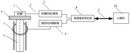
[0026] see figure 1 , which is the structure and components of the high-precision dynamic angle measuring device targeted by the present invention. The dynamic angle measurement device of the present invention includes a spatial four-frequency differential laser gyro 1, a flexible cable 2, a gyro control / demodulation circuit 3, a circular induction synchronizer 7, an induction synchronizer demodulation circuit 8, and an angle increment signal processing circuit 4, 422 A bus 5, and an angle measurement computer 10, wherein the spatial four-frequency differential laser gyroscope 1 is installed on the rotating shaft 9 to be measured via the transition plate 6, and the two are rigidly connected by screws or mechanical fastening devices. The transition plate 6 is made of stainless steel, which has the advantages of high hardness, good stability, non-magnetic conduction, etc., ...


PUM


Abstract

The invention belongs to the technical field of high-precision angle measurement, and relates to a high-precision dynamic angle measuring device and method. The high-precision dynamic angle measuring device comprises a spacial four-frequency differential laser gyro, a flexible cable, a gyro control / demodulator circuit, a round inductosyn, an inductosyn demodulator circuit, an angle increment signal processing circuit, a connection bus, and an angle measuring computer. In the high-precision dynamic angle measuring method, the measured inertia spacial angular speed projection component on the sensitive axis of spacial four-frequency differential laser gyro is utilized to precisely obtain the inertia spacial angular speed component on the gyro sensitive axis in the current position by using an interpolation method according to the angular position output of the round inductosyn; moreover, in the gyro output, the current inertia spacial angular speed component is eliminated, and thus the angle measurement precision is largely improved. For the output of spacial four-frequency differential laser gyro, the angular speed integral time can reach the microsecond level. A spacial four-frequency differential laser gyro with a scale coefficient, which can be highly segregated, is adopted; and the provided device and method have the advantages of high angle measurement precision, large dynamic range, no counter-torque effect on measure carrier, small temperature coefficient, and good practical application value.

Description

technical field [0001] The invention belongs to high-precision dynamic angle measurement technology, and relates to a high-precision dynamic angle measurement device and method. Background technique [0002] Angle measurement is an important part of geometric measurement technology. At present, there are mainly the following types of angle measurement methods in industry: mechanical angle measurement method, electromagnetic angle measurement method, optical angle measurement method and photoelectric angle measurement method. The mechanical measurement method is represented by a multi-tooth indexing table, which has a simple structure and low cost, but usually has the disadvantages of large equipment and cannot be used for real-time dynamic measurement; the electromagnetic angle measurement method is represented by an induction synchronizer, which runs fast and stable Reliable, but has the disadvantages of high coupling with the system under test and high assembly precision r...

Claims


Application Information

Patent Timeline
Patent Type & Authority Applications(China)
IPC IPC(8): G01C1/00
CPCG01C19/64
Inventor 王京献陈林峰傅鑫
Owner FLIGHT AUTOMATIC CONTROL RES INST
Why Eureka
Try Eureka