
Self locking system of MT (Manual Transmission) gear shifting mechanism

A manual transmission and shifting mechanism technology, applied in mechanical equipment, transmission control, components with teeth, etc., can solve problems such as the inability to ensure a clear gear position, the inability to play a neutral gear and the accurate positioning of each gear position.

Inactive Publication Date: 2015-11-25
SAIC-GM-WULING AUTOMOBILE CO LTD
View PDF6 Cites 2 Cited by
  • Summary
  • Abstract
  • Description
  • Claims
  • Application Information

AI Technical Summary

Problems solved by technology

[0004] In the actual design and manufacturing process, there is a distance between the shift head and the shift block, and a distance between the shift fork and the tooth sleeve. Therefore, to realize the complete self-locking function, the entire transmission shift mechanism must be Self-locking control is implemented, while traditional manual transmissions and other patents related to manual transmission self-locking only realize the self-locking control of the shift fork shaft assembly or the self-locking control of the shift control assembly, but due to the two spacing The existence of the gear shift mechanism, only one of the three assemblies in the shifting mechanism is self-locking, which cannot achieve the accurate positioning of the neutral gear and each gear position, nor can it guarantee the clear function of the gear position.

Method used


Image

  • Self locking system of MT (Manual Transmission) gear shifting mechanism
  • Self locking system of MT (Manual Transmission) gear shifting mechanism
  • Self locking system of MT (Manual Transmission) gear shifting mechanism

Examples


Embodiment Construction

[0037] The following with attached Figure 1 to Figure 10 The manual transmission shift mechanism self-locking system of the present invention will be further described in detail.

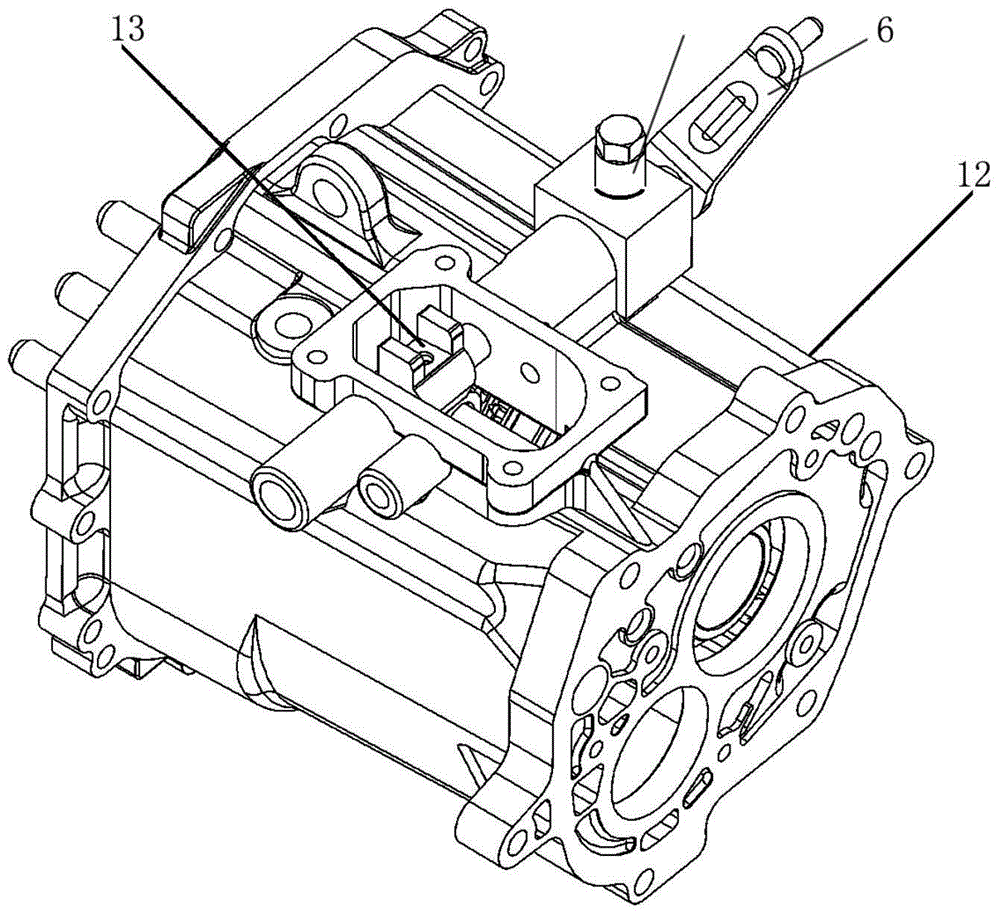
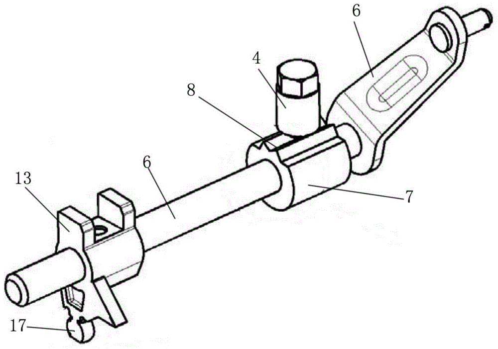
[0038] For the self-locking system of manual transmission shift mechanism of the present invention, please refer to Figure 1 to Figure 10, including a synchronizer assembly 1, a shift fork shaft assembly 2 and a shift operation assembly 3, the synchronizer assembly 1 is set on the transmission shaft, the shift fork shaft assembly 2 and the synchronizer assembly into a sliding connection, the shift operation assembly 3 is connected to the shift fork shaft assembly 2, the shift operation system is connected with a positioning spring ball device that can lock the shift operation system, and the synchronization A self-locking device that can lock the synchronizer assembly 1 is provided in the synchronizer assembly 1, and the positioning spring ball device includes a sleeve 4 and a self-locking spring...


PUM


Abstract

The invention discloses a self locking system of an MT (Manual Transmission) gear shifting mechanism. The self locking system comprises a synchronizer assembly, a shifting fork shaft assembly and a gear shifting operation assembly, wherein the synchronizer assembly, the shifting fork shaft assembly and the gear shifting operation assembly are sequentially connected; a gear shifting operation system is connected with a positioning spring ball device comprising a sleeve and a self locking spring ball which is elastically arranged in the sleeve; a self locking device is arranged in the synchronizer assembly; the gear shifting operation assembly comprises a gear shifting rocker arm which is provided with a waveform convex plate; the self locking spring ball leans against a concave part which is formed by a waveform surface of the waveform convex plate; a neutral position positioning groove is formed in the synchronizer assembly; the self locking device comprises a neutral position positioning spring; the neutral position positioning spring is arranged in the neutral position positioning groove in a clamping way or is deviated from the neutral position positioning groove. According to the self locking system of the MT gear shifting mechanism, disclosed by the invention, the structure is simple, respective and mutual non-interference self locking on the synchronizer assembly and the gear shifting operation assembly is realized, accurate positioning of the synchronizer assembly and the gear shifting operation assembly is ensured, the situation that a driver has a clear gear sense during a gear shifting process is ensured, and gear clearness is ensured.

Description

technical field [0001] The invention relates to a self-locking system, in particular to a self-locking system of a shift mechanism of a manual transmission. Background technique [0002] The self-locking mechanism is an important part of the transmission. It can ensure that the transmission is accurately positioned in the neutral gear and each gear during the process of shifting gears and removing gears. [0003] The entire transmission shifting mechanism includes shifting operation assembly, shift fork shaft assembly and synchronizer assembly. The shifting operation assembly is controlled by human hands, and the shifting head of the shifting operation assembly is located Inside the shift slot, the shift paddle pushes the shift block, so that the shift control assembly controls the shift fork shaft assembly. , the shift fork shaft pushes the gear sleeve to move, thereby realizing the control of the shift fork shaft assembly to the synchronizer assembly, and the control of t...

Claims


Application Information

Patent Timeline
IPC IPC(8): F16H63/34
CPCF16H63/34F16H63/3408F16H2306/00
Inventor 柯建峰何耀华黄元毅巫绍宁杨灿刘垚均杜宏斌
Owner SAIC-GM-WULING AUTOMOBILE CO LTD
Learn More