
A centering mechanism for horizontal ultra-high pressure sterilization equipment

An ultra-high pressure sterilization and equipment matching technology, which is applied in food science, food preservation, application and other directions, can solve the problems of the plugs entering and exiting the ultra-high pressure cylinder not smoothly, easily damaging the plug sealing ring, and the axes are not easy to coincide, etc. Achieve the effect of eliminating the coaxial adjustment link, improving the support rigidity, and improving the relative movement accuracy of the coaxial

Inactive Publication Date: 2018-11-02
CHINA AGRI UNIV
View PDF5 Cites 0 Cited by
  • Summary
  • Abstract
  • Description
  • Claims
  • Application Information

AI Technical Summary

Problems solved by technology

However, since the plugs on both sides and the ultra-high pressure cylinder are installed on different mobile devices, the axes of the three are not easy to coincide on a straight line, which makes it difficult for the plug to enter and exit the ultra-high pressure cylinder smoothly, and the seal on the plug is easily damaged. Frequent replacement of the sealing ring will not only affect the production efficiency but also increase the operating cost. Therefore, effectively solving the alignment between the plug and the ultra-high pressure cylinder is the key issue to improve the technical performance of the horizontal ultra-high pressure sterilization equipment

Method used


Image

  • A centering mechanism for horizontal ultra-high pressure sterilization equipment
  • A centering mechanism for horizontal ultra-high pressure sterilization equipment
  • A centering mechanism for horizontal ultra-high pressure sterilization equipment

Examples


Embodiment Construction

[0026]The present invention provides a centering mechanism for horizontal ultra-high pressure sterilization equipment. The present invention will be further described below in conjunction with the accompanying drawings and specific implementation methods.

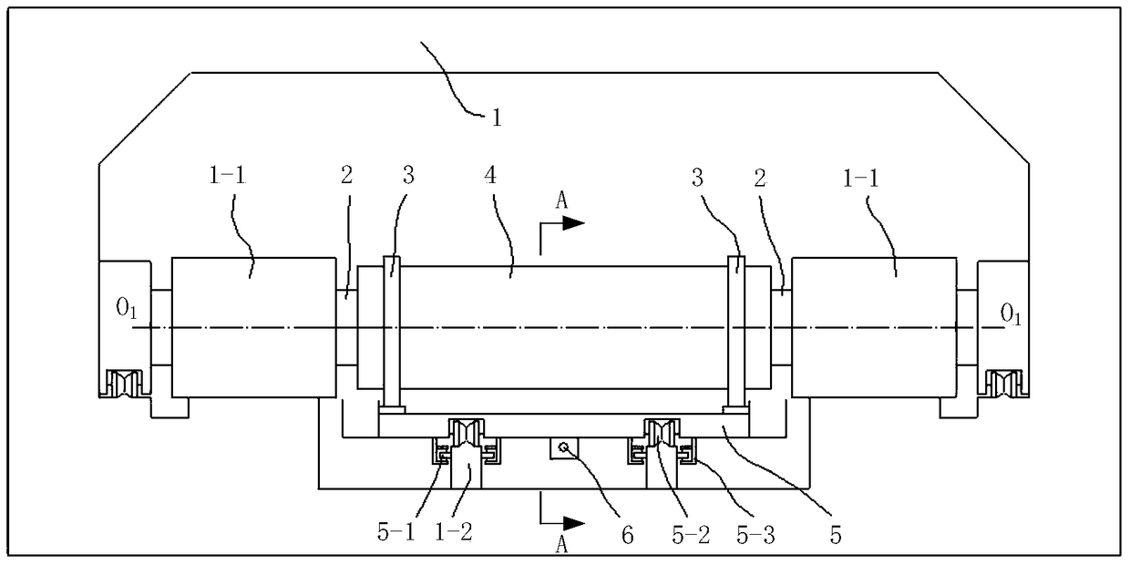
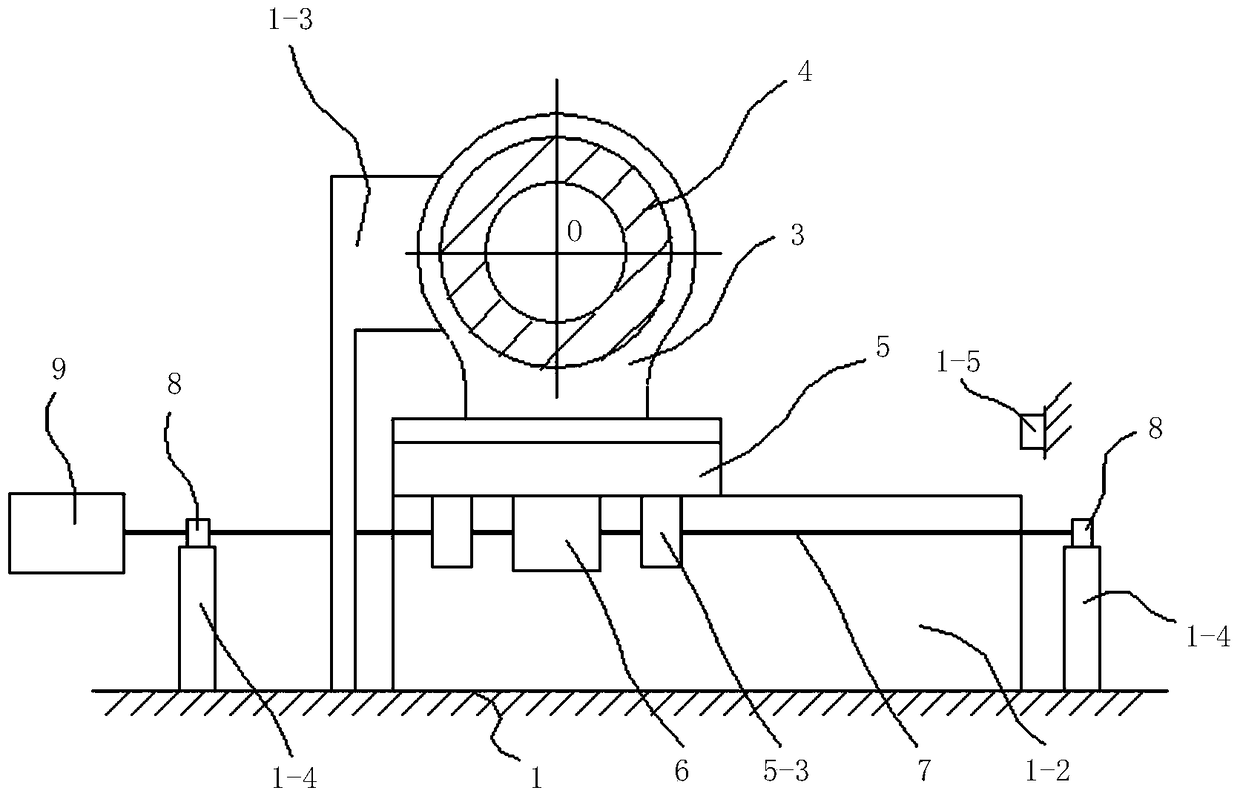
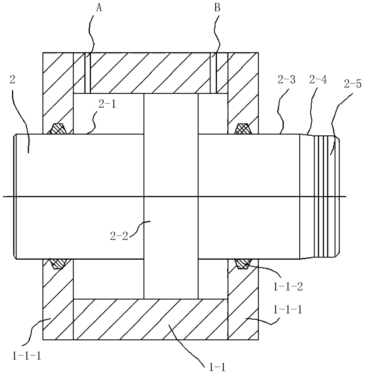
[0027] Such as figure 1 and figure 2 As shown, a centering mechanism of a horizontal ultra-high pressure sterilization equipment provided by the present invention includes a frame 1, a cylinder body 1-1, a trolley rail beam 1-2, a centering positioning block 1-3, and a bearing support column 1- 4. Positioning block 1-5 for trolley feeding position, piston plug 2, cylinder body fixing seat 3 and trolley frame 5: left and right cylinder body 1-1, left and right trolley guide rail beam 1-2, left and right alignment positioning Blocks 1-3, front and rear bearing support columns 1-4, trolley feeding position positioning blocks 1-5 and frame 1 are integrated; The guide rail beam 1-2 is vertically symmetrically arranged on the ...


PUM


Abstract

The invention provides a horizontal-type ultra-high pressure sterilization equipment aligning mechanism. According to the horizontal-type ultra-high pressure sterilization equipment aligning mechanism, cylinder bodies (1-1), trolley guide rail beams (1-2), aligning positioning blocks (1-3) and a frame (1) are connected into a whole, the axis of the left cylinder body (1-1) and the axis of the right cylinder body (1-1) are on the same straight line, and circle centers of concaved circular cambered surfaces of the left aligning positioning block (1-3) and the right aligning positioning block (1-3) and the axes of the left cylinder body (1-1) and the right cylinder body (1-1) are on the same straight line; the cylinder bodies (1-1) are matched with piston-type plugs (2) to form hydraulic oil cylinders, and the axes of the left piston-type plug (2) and the right piston-type plug (2) are on the same straight line; an ultra-high pressure barrel body (4) is fixed to a trolley frame (5) through barrel body fixing seats (3), the trolley frame (5) is pulled by a lead screw nut mechanism driven by a servo motor to move along guide rails on the trolley guide rail beams (1-2), positioning is achieved through contact between the barrel body fixing seats (3) and the aligning positioning blocks (1-3), and the situation that the axis of the ultra-high pressure barrel body (4) and the axes of the left piston-type plug (2) and the right piston-type plug (2) are on the same straight line is achieved.

Description

technical field [0001] The invention belongs to horizontal ultrahigh pressure sterilization equipment in food processing, in particular to a centering mechanism of horizontal ultrahigh pressure sterilization equipment. Background technique [0002] Ultra-high pressure sterilization is a new type of food cold sterilization technology that packs food materials into a high-pressure container filled with water and sterilizes them under a pressure of 400MPa-600MPa. It not only helps to maintain the physiological activity of food functional components, but also It is also beneficial to maintain the color, aroma, taste and nutrients, and has become an efficient food sterilization method. Due to the low working height, the horizontal ultra-high pressure sterilization equipment is convenient for manual feeding and discharging, and can be made into a large-volume ultra-high pressure container, which is suitable for application in food processing plants. Sterilization equipment. This...

Claims


Application Information

Patent Timeline
Patent Type & Authority Patents(China)
IPC IPC(8): A23L3/015
CPCA23L3/0155
Inventor 庞昌乐孙志健沈群
Owner CHINA AGRI UNIV
Learn More