
A Method of Suppressing Torque Fluctuation of Surface-mounted Permanent Magnet Synchronous Motor Using Current Harmonics

A permanent magnet synchronous motor, current harmonic technology, applied in torque ripple control and other directions, can solve the problems of inaccurate current zero-crossing detection, complex algorithm, wrong compensation and so on

Active Publication Date: 2018-03-09
HOHAI UNIV
View PDF3 Cites 0 Cited by
  • Summary
  • Abstract
  • Description
  • Claims
  • Application Information

AI Technical Summary

Problems solved by technology

However, this type of method needs to add new hardware, the algorithm is more complicated, and because the current zero-crossing detection is not accurate, it is easy to cause false compensation
[0004] In recent years, people have gradually realized that it is difficult to completely eliminate the torque fluctuations of permanent magnet synchronous motors by simply suppressing back EMF harmonics and current harmonics, and it is often necessary to sacrifice some other performance of the system in the process of suppressing harmonics. Therefore, some experts proposed to improve the performance of the motor system from the perspective of harmonic utilization, which provides a new idea for the torque fluctuation suppression of permanent magnet synchronous generators.
However, the generation of permanent magnet synchronous motor torque fluctuation is the result of the joint action of back electromotive force and current harmonics, and the harmonic components of back electromotive force and current are relatively complex. If current harmonics are to be used to suppress torque fluctuations, it is necessary The mechanism of action between the two harmonics must be deeply analyzed
Due to the lack of research on the mechanism of harmonic action, current harmonic utilization technology has been greatly limited

Method used


Image

  • A Method of Suppressing Torque Fluctuation of Surface-mounted Permanent Magnet Synchronous Motor Using Current Harmonics
  • A Method of Suppressing Torque Fluctuation of Surface-mounted Permanent Magnet Synchronous Motor Using Current Harmonics
  • A Method of Suppressing Torque Fluctuation of Surface-mounted Permanent Magnet Synchronous Motor Using Current Harmonics

Examples


Embodiment 1

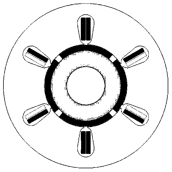
[0111] 101: figure 2 It is a finite element model of a 4-pole 6-slot double-layer winding surface-mounted permanent magnet synchronous motor. The rated frequency of the motor is 50Hz, the rated speed is 1500r / min, and the effective value of the rated current is 3A, that is, I 1 = 4.24A. Surface-mounted permanent magnet synchronous motors usually use i d =0 control mode to control, that is, ψ 1 =0.

[0112] 102: The three-phase electromotive force waveform of the motor can be obtained through finite element simulation, such as image 3 (a) shown. Further obtain the spectrum distribution of each harmonic of the back EMF and the amplitude of each harmonic through Fourier transform, such as image 3 (b) shown.

[0113] 103: by image 3 (b) It can be seen that the 5th and 7th orders of the back electromotive force waveform are the main harmonics, and the amplitudes of other harmonics are less than 2% of the fundamental wave amplitude, so other harmonics can be ignored, foc...

Embodiment 2

[0122] 101: Figure 5 It is a 4-pole 12-slot single-layer winding surface-mount permanent magnet synchronous motor finite element model. The rated frequency of the motor is 50Hz, the rated speed is 1500r / min, and the effective value of the rated current is 3A, that is, I 1 = 4.24A. Surface-mounted permanent magnet synchronous motors usually use i d =0 control mode to control, that is, ψ 1 =0.

[0123] 102: The three-phase electromotive force waveform of the motor can be obtained through finite element simulation, such as Image 6 (a) shown. Further obtain the spectrum distribution of each harmonic of the back EMF and the amplitude of each harmonic through Fourier transform, such as Image 6 (b) shown.

[0124] 103: by Image 6(b) It can be seen that the 5th and 7th orders of the back electromotive force waveform are the main harmonics, and the amplitudes of other harmonics are less than 2% of the fundamental wave amplitude, so other harmonics can be ignored, focusing o...


PUM


Abstract

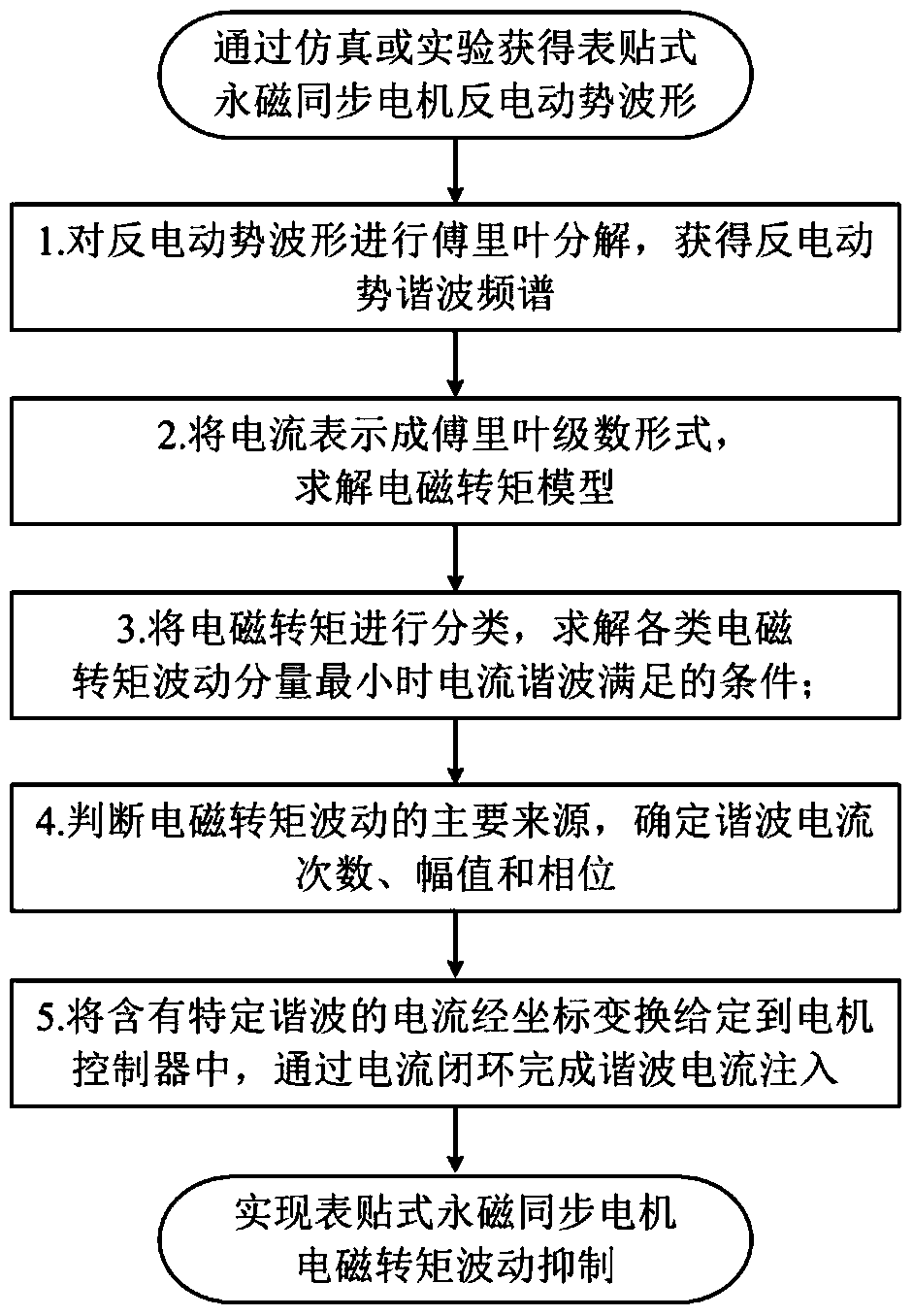
The invention discloses a method for restraining torque ripple of a surface-mounted permanent magnet synchronous motor by use of current harmonic waves. The method comprises steps of performing Fourier decomposition on back EMF waveforms of the permanent magnet synchronous motor to obtain a frequency spectrum of the back EMF and the amplitude of harmonic waves every time; representing current as Fourier series and solving an electromagnetic torque model based on three-phase back EMF and the current expression; classifying the electromagnetic torque according to different components of harmonic waves and solving conditions that the current harmonic waves satisfy during the smallest electromagnetic torque ripple; judging the main sources of the electromagnetic torque ripple and determining numbers, amplitudes and phase positions of the current harmonic waves according to characteristics of the back EMF waveforms; and accessing current containing specific harmonic waves into a three-phase winding of the permanent magnet synchronous motor to restrain electromagnetic torque ripple of the motor. Thus, the electromagnetic torque ripple of the surface-mounted permanent magnet synchronous motor can be effectively restrained; a new idea is provided for restraining of the electromagnetic torque ripple; and the method can be further used for torque ripple restraining of other types of surface-mounted permanent magnet synchronous motor.

Description

technical field [0001] The invention relates to the technical field of torque fluctuation suppression of surface-mounted permanent magnet synchronous motors, in particular to a method for suppressing torque fluctuations of surface-mounted permanent magnet synchronous motors by using current harmonics. Background technique [0002] Surface-mounted permanent magnet synchronous motors have high efficiency, power factor and torque density, so they are widely used in elevators, wind power, hybrid vehicles and many other industrial fields. For surface-mounted permanent magnet synchronous motors, in theory, if the back electromotive force and current of the motor are ideal sine waves, the motor can generate constant electromagnetic torque. However, in fact, on the one hand, due to factors such as the distribution form of the windings used by the motor itself, the cogging effect, and the arrangement of magnetic poles, the air gap magnetic field of the motor is distorted, generating ...

Claims


Application Information

Patent Timeline
Patent Type & Authority Patents(China)
IPC IPC(8): H02P6/10
Inventor 陈浈斐马宏忠
Owner HOHAI UNIV
Learn More